Description
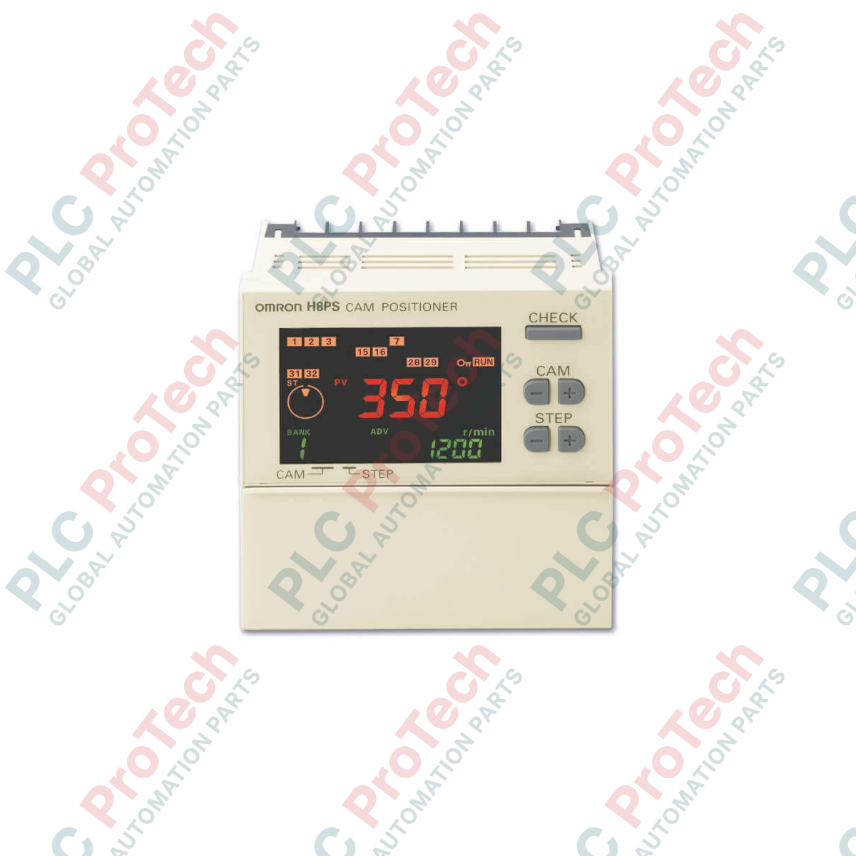
Designed to optimize mechanical synchronization on automation lines, the Omron H8PS-8B electronic cam positioner replaces traditional mechanical cams with high-speed microcomputer-based precision. This compact 1/4 DIN (96 x 96 mm) panel-mount controller processes absolute encoder feedback to actuate 8 NPN transistor outputs at exact angular positions, minimizing mechanical wear and maximizing setup flexibility.
Features
- Clear LCD display with a high-visibility backlight for real-time monitoring of angle and speed.
- Flexible encoder rotation direction configuration (CW/CCW) utilizing a built-in hardware DIP switch.
- Support for high-precision absolute rotary encoders to maintain position data during power cycles.
- Easy-to-program cam outputs with direct manual or teaching-mode parameter adjustments.
- Compact 67.5 mm depth behind panel allowing tight integration within standard control enclosures.
Applications
- High-speed packaging and cartoning machinery synchronization.
- Form-fill-seal (FFS) systems for precise timing of cutting and sealing jaws.
- Press feeding machinery and metal stamping automation.
- Rotary indexing tables and assembly conveyor alignment.
Technical Specifications Table
| Parameter |
Specification Value |
| Manufacturer |
Omron |
| Model |
H8PS-8B |
| Series |
H8PS |
| Mounting Type |
On-panel (Flush Mount) |
| Physical Dimensions |
96 x 96 x 67.5 mm (1/4 DIN) |
| Operating Voltage |
24 VDC (Operating range: 20.4 to 26.4 VDC) |
| Output Configuration |
8 NPN Transistor Outputs (30 VDC, 100 mA max.) |
| Compatible Encoder Input |
Omron Absolute Encoder (E6C3-AG5C-C / E6F-AG5C-C) |
| DIP Switch Settings |
CW/CCW direction select; Resolution switch (256/360) |
| Backup Memory |
EEPROM (Non-volatile, over 100,000 write cycles) |
| Operating Temperature Range |
-10 to 55 degC (no icing or condensation) |
| Weight |
Approx. 300 g |
| Shipping Weight (Calculated) |
1.5 kg |
| Package Dimensions (Calculated) |
150 x 150 x 120 mm |
Connections and Interfaces
| Terminal ID / Pin |
Function / Circuit Assignment |
| Power Terminals |
+24 VDC Supply Input and 0 VDC Reference Ground |
| INPUT (RUN / TEST) |
External mode selection switch input |
| OUT 1 to OUT 8 |
Discrete NPN outputs to signal load/valves |
| OUT COM |
Common terminal for NPN transistor outputs |
| Encoder Connector |
Multi-pin dedicated absolute encoder interface input |
Empirical Engineering Insights
Alternative Models & Compatibility
The H8PS-8B utilizes a dedicated 8-output panel design. For projects requiring DIN rail installation instead of panel flush-mounting, use the H8PS-8BF variant. To transition seamlessly between these form factors, verify that your absolute encoder resolutions (typically 256 or 360 points) match the hardware toggle switches on the rear plate of the replacement module.
Application Pitfalls & Engineering Notes
Encoder signal line interference is a common source of synchronization drift. Avoid routing the absolute encoder interface cable parallel to high-power motor phases or variable frequency drive (VFD) supply lines. Maintain physical separation and ensure the external encoder shield is grounded at a single, low-impedance ground point on the controller panel side.
Commissioning & Wiring Tips
When establishing the mechanical home reference on initial power-up, use the unit's zero-point shift/teaching function. This allows the controller's internal zero reference to align electronically with the machine's physical dead center without needing physical shaft repositioning of the rotary encoder.
Installation Guidelines
CRITICAL SYSTEM SAFETY WARNING
Isolate all 24 VDC power sources feeding the H8PS-8B and adjacent input/output field devices prior to panel mounting, maintenance, or wiring operations. Failure to de-energize external output lines may damage the NPN output transistors or trigger unexpected actuator motion.
1
Prepare a 92 x 92 mm panel cutout conforming to standard 1/4 DIN structural specifications.
2
Set the rear-mounted DIP switches for the target rotation direction (CW or CCW) and matching encoder resolution before inserting the device.
3
Insert the controller housing through the front of the cutout and secure it in place using the supplied side-tension mounting brackets.
4
Terminate the absolute encoder connector, apply 24 VDC external supply to power inputs, and proceed with digital functional validation.