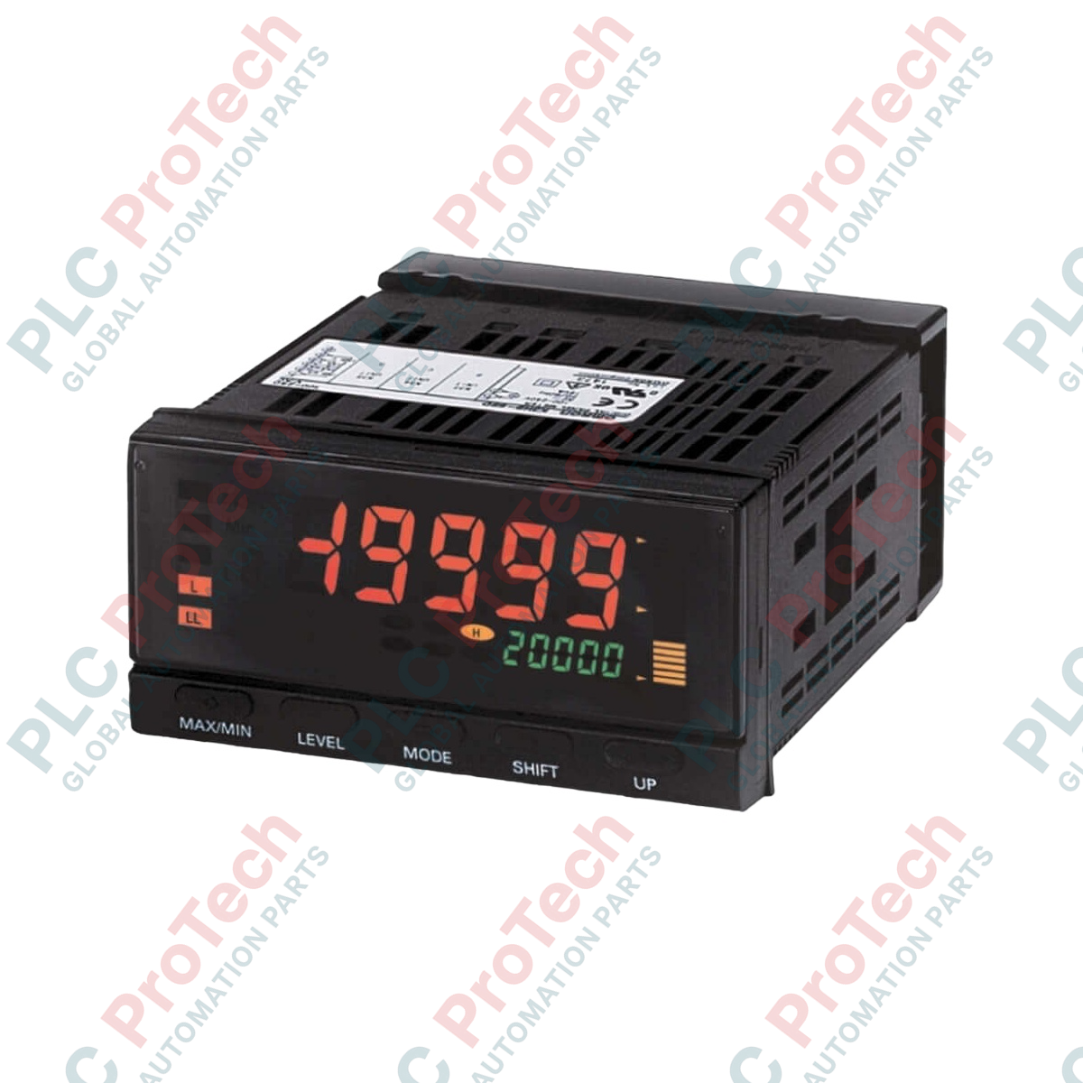
Description
Engineered for high-speed rotational measurement, the Omron K3HB-RNB-C2 serves as a highly precise digital rotary pulse indicator within demanding industrial automation frameworks. Designed to support rotary pulse inputs up to 50 kHz, this device provides instantaneous, high-resolution velocity and rotation metrics. The unit integrates an NPN/voltage pulse sensor input configuration and utilizes four independent SPST-NO relay outputs for critical limit monitoring (HH, H, L, LL). Its multi-color display dynamically changes color based on alarm status, providing field operators with immediate visual confirmation of system performance.
Features
-
High-Speed Pulse Processing: Capable of accurate signal evaluation up to 50 kHz for rapid shaft rotation and line speed monitoring.
-
Versatile Sensor Input: Designed to interface natively with NPN open-collector or voltage pulse sensors.
-
Quad Limit Relay Outputs: Provides dedicated SPST-NO contacts for High-High (HH), High (H), Low (L), and Low-Low (LL) limit controls.
-
Dynamic Visual Feedback: Visual alert status communicated through a dual-color process value display.
-
Robust Environment Adaptation: Engineered to maintain operations in ambient temperatures ranging from -10 to 55 degC.
Applications
- Rotational speed (RPM) monitoring of industrial electric motors and turbines.
- Conveyor line velocity tracking and throughput measurement in packaging systems.
- Flow meter pulse integration for volumetric rate monitoring.
- Operational safety interlock systems requiring overspeed or underspeed trip detection.
Technical Specifications Table
| Parameter |
Value / Specification |
| Manufacturer |
Omron |
| Model Number |
K3HB-RNB-C2 |
| Product Series |
K3HB Series |
| Input Sensor Code |
NB (NPN input / voltage pulse input) |
| Relay Output Configuration |
C2 (Relay contact: HH, H, LL, L; SPST-NO each) |
| Nominal Supply Voltage |
100 to 240 VAC |
| Maximum Measurement Frequency |
50 kHz |
| Ambient Operating Temperature |
-10 to 55 degC (no icing or condensation) |
| Ambient Operating Humidity |
25% to 85% RH |
| Storage Temperature Range |
-25 to 65 degC |
| Maximum Operating Altitude |
2000 m |
| Device Base Weight |
Approx. 300 g |
| Shipping Weight (Calculated) |
1.5 kg |
Empirical Engineering Insights
Alternative Models & Compatibility
The K3HB series serves as the modern standard update to legacy Omron K3N indicators. While functional similarities exist, please note that wiring structures and rear terminal blocks differ significantly. Panel cutouts are standardized, but back-of-panel depth clearances must be verified during system retrofits to accommodate the output terminal configuration on the K3HB-RNB-C2.
Application Pitfalls & Engineering Notes
When utilizing the maximum 50 kHz measurement range, standard sensor wiring is highly susceptible to electromagnetic interference (EMI). Run signal lines in independent, grounded steel conduits separate from high-current motor leads or Variable Frequency Drive (VFD) output cables to prevent false triggering. Keep the cable length to the sensor as short as possible to prevent signal attenuation.
Commissioning & Wiring Tips
Ensure that the internal parameter settings match the connected sensor type (NPN open-collector versus voltage pulse). Failing to configure this software parameter correctly may result in zero pulse registration or risk overloading the internal signal pull-up circuit. Always apply shielded twisted-pair (STP) cabling for the input connections.
Installation Guidelines
CRITICAL WARNING: Prior to wiring or mounting the K3HB-RNB-C2 unit, verify that all incoming AC power distribution sources are physically locked out and tagged out. Hazardous voltages remain present on terminal contacts during operation. Do not touch terminals while supply power is active.
1
Prepare a standardized 1/8 DIN panel cutout (92 mm x 45 mm) and slide the unit through the panel front, ensuring the rubber sealing gasket is flat against the surface.
2
Secure the unit into the panel using the provided side mounting fixtures, tightening the screws evenly to ensure a secure dust and water-resistant fit.
3
Attach the sensor input cables to the designated NB terminals using properly sized crimped ferrule connectors to ensure permanent gas-tight contacts.
4
Connect the 100 to 240 VAC power line to the primary power input terminals, re-check terminal polarity, and proceed to device parameter configuration.