Description
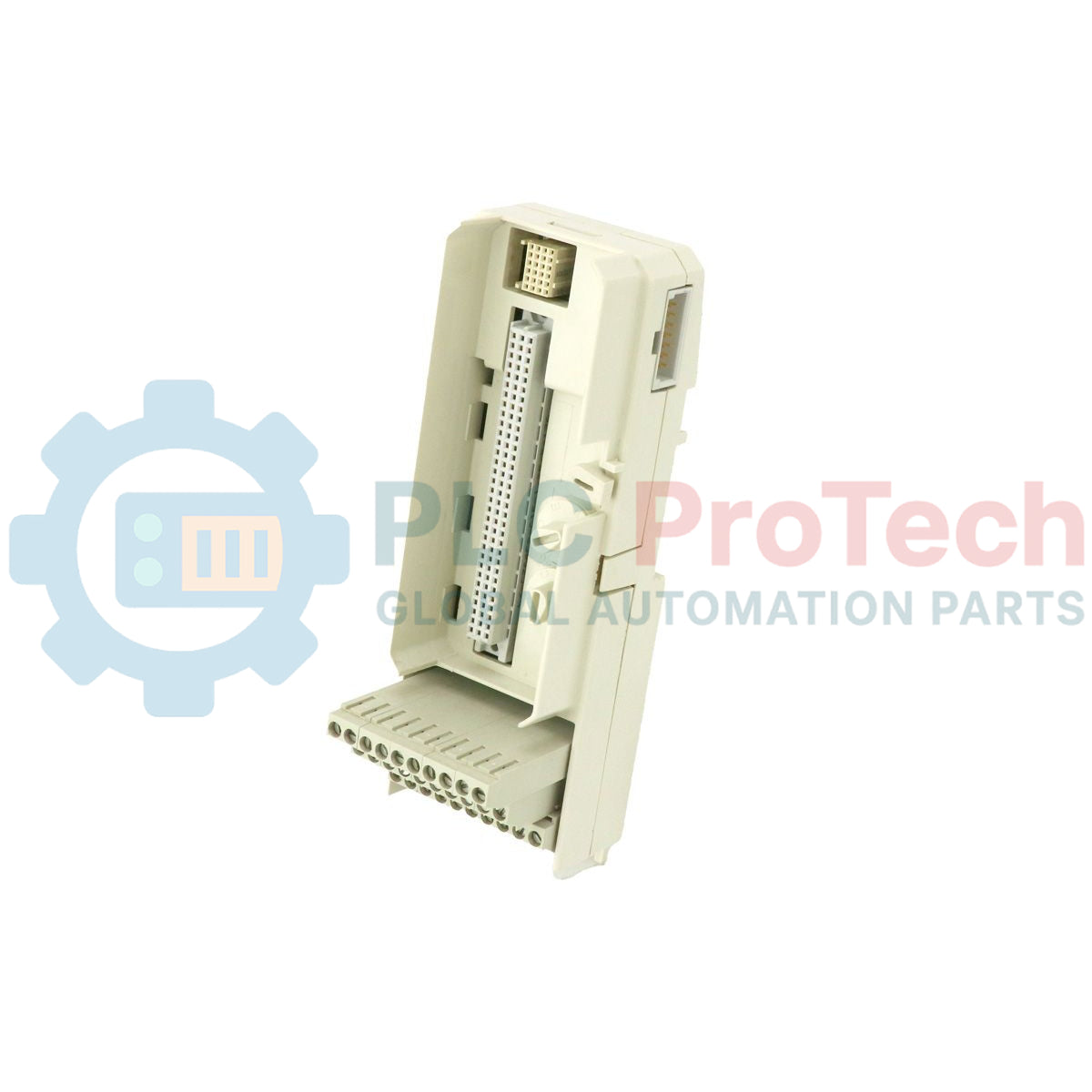
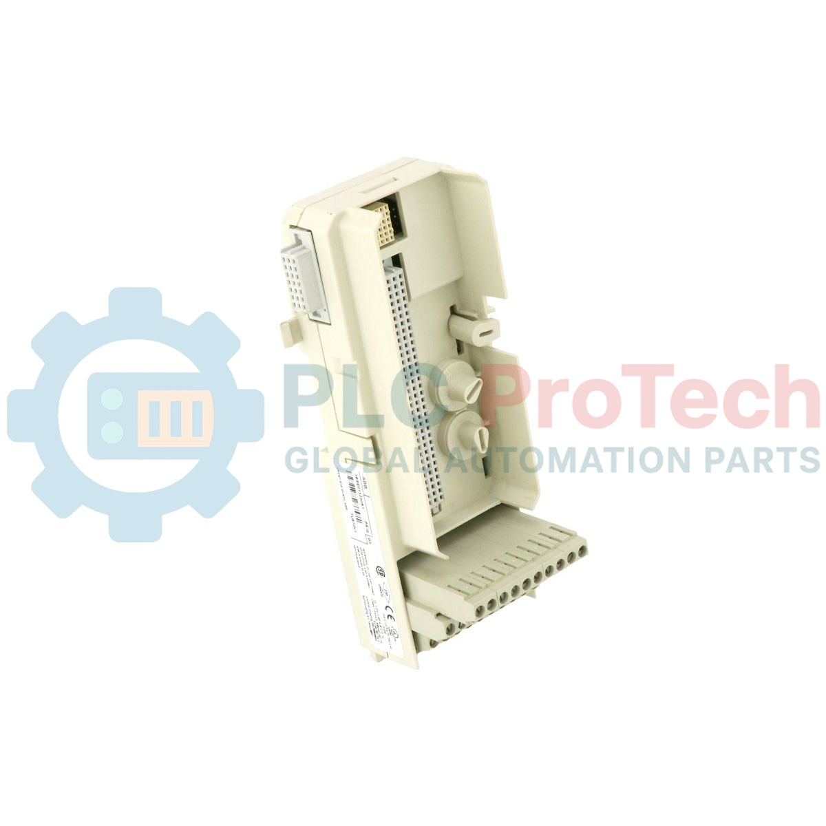
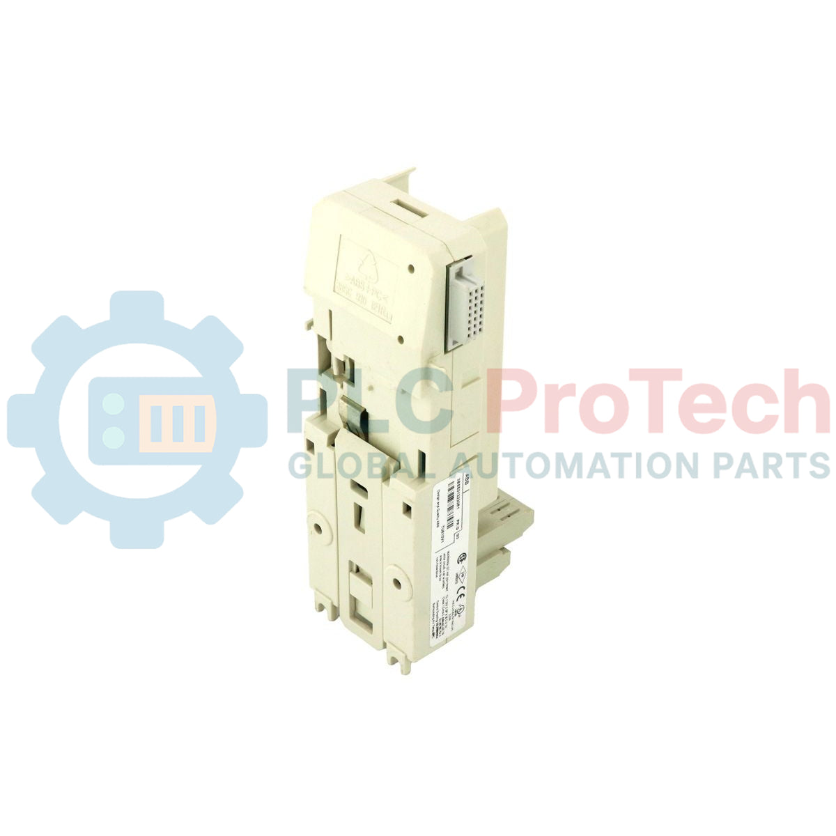
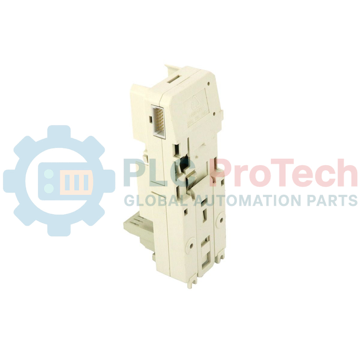
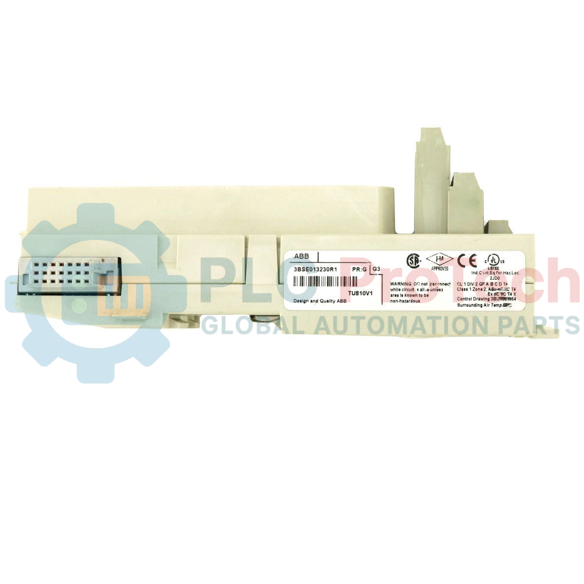
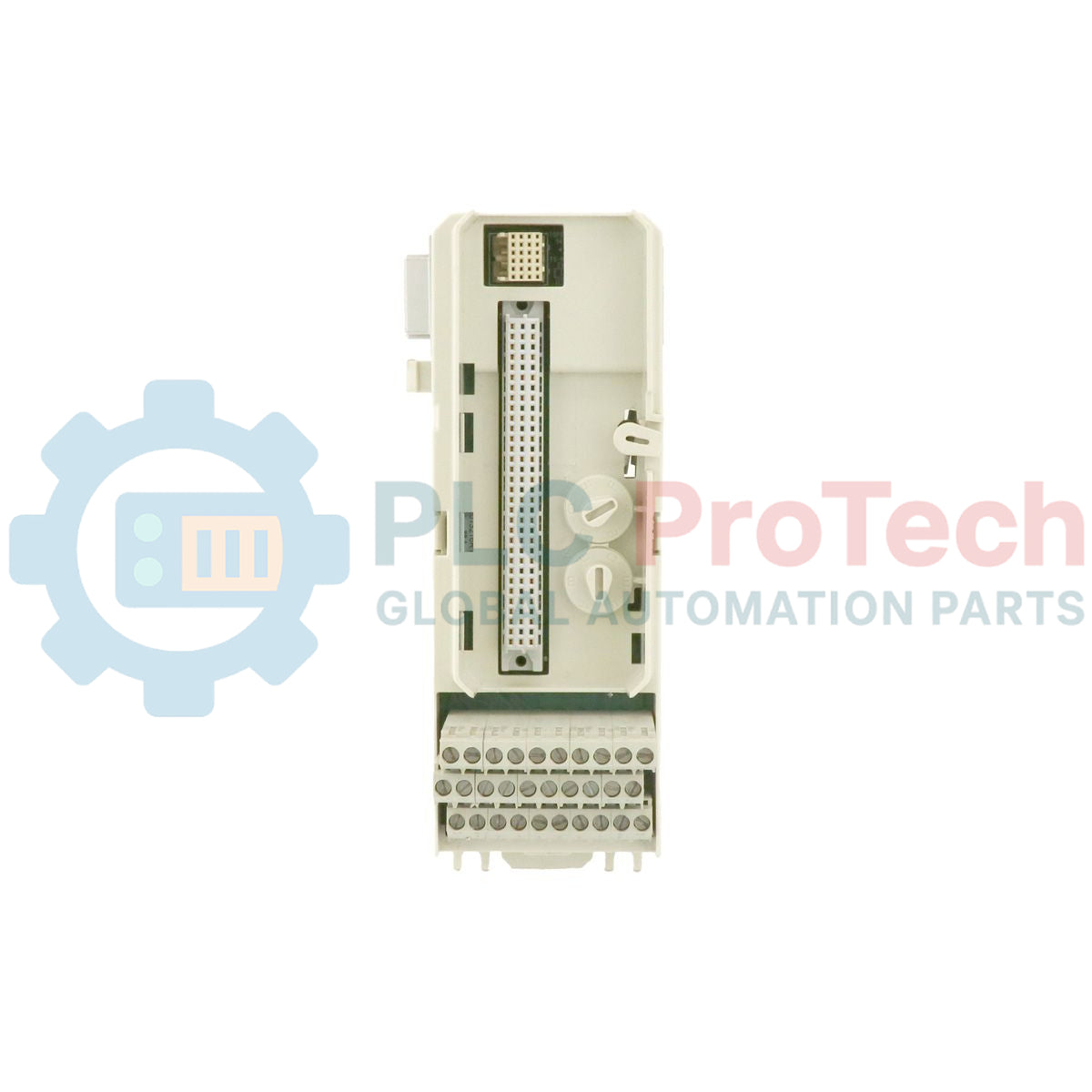
Serving as a robust connection interface within the S800 I/O distributed automation architecture, the ABB TU810V1 (part number 3BSE013230R1) acts as a compact module termination unit designed to route signals reliably between field wiring and active I/O process modules. This unit accommodates up to 16 independent channels, operating at a maximum rating of 50V, making it a critical component for high-density cabinet layouts where footprint optimization is vital.
Features
-
High-Density Compact Footprint: Allows direct horizontal or vertical DIN-rail mounting to minimize cabinet space requirements.
-
16-Channel Configuration: Routes up to 16 individual I/O channels alongside dual process voltage connections.
-
Mechanical Coding Keys: Prevents mismatched module insertion, safeguarding the active electronics from field configuration errors.
-
Integrated Modulebus Link: Seamlessly transfers signals and power to adjacent units without external jumper cables.
-
Dual Voltage Distribution: Includes 2 isolated groups with commoned terminal distribution points.
Applications
- Advant OCS and System 800xA distributed control architectures.
- Petrochemical, power generation, and water treatment field-instrumentation processing.
- High-density electrical marshaling cabinets and field junction boxes.
Technical Specifications
| Parameter |
Specification Value |
| Manufacturer |
ABB |
| Model Designation |
TU810V1 |
| Product ID / SKU |
3BSE013230R1 |
| Series |
S800 I/O |
| Type |
Compact Module Termination Unit (MTU) |
| Number of Channels |
16 channels |
| Rated Voltage |
50 V DC / AC maximum |
| Rated Current |
3 A per channel maximum |
| Connection System |
Single-wire screw clamp terminals |
| Conductor Size |
0.2 to 2.5 mm² (24 to 14 AWG) |
| Modulebus Load |
Negligible (passive routing) |
| Dimensions (H x W x D) |
165 mm x 45 mm x 72 mm |
| Weight |
0.20 kg |
| Commodity Code |
85389091 |
Connections and Interfaces
| Terminal / Connector Point |
Function / Circuit Assignment |
| Terminals 1 to 16 |
I/O Channel connections (Signals 1 to 16) |
| Terminals 17 & 18 |
Process Voltage Common 1 (distribution bus) |
| Terminals 19 & 20 |
Process Voltage Common 2 (distribution bus) |
Empirical Engineering Insights
Alternative Models & Compatibility
The TU810V1 serves as a direct, drop-in evolution of the legacy TU810 compact MTU. The V1 variant features improved thermal tolerance and mechanical housing updates, ensuring absolute backward-compatibility with all existing S800 I/O modules that require a 50V connection interface. If upgrading from non-V1 units, no software modifications or engineering changes are required in the System 800xA or Control Builder environments.
Application Pitfalls & Engineering Notes
While rated for 50V operational limits, designers must verify that the total accumulated current across all 16 connected channels does not exceed the capacity of the power distribution source. In highly compact enclosures, field wiring must be routed systematically to prevent localized heating near the screw terminals, which could accelerate degradation of the adjacent active I/O modules.
Commissioning & Wiring Tips
To ensure noise immunity in electromagnetic interference (EMI) heavy environments, signal cables should be shielded up to the cabinet entrance, and shields must be grounded to a designated bar separate from the MTU. Ensure that the plastic coding keys on the MTU base are properly configured to match the corresponding module type before power-up to prevent physical component damage during hot-swapping procedures.
Installation Guidelines
CRITICAL WARNING: Complete physical isolation and de-energization of the field supply and Modulebus backplane are mandatory before mounting, unmounting, or wiring the MTU. Failure to isolate power may cause electrical arcing, module destruction, or hazardous field conditions.
1
Mount the TU810V1 MTU onto a grounded 35mm horizontal DIN rail by latching the top groove and snapping the lower locking tab onto the rail.
2
Slide the unit laterally along the DIN rail to connect its Modulebus port directly to the adjacent MTU/Modulebus optical port, ensuring the connection latches completely.
3
Strip field signal and distribution wires to 6mm, insert them into the screw terminals (terminals 1-20), and torque them uniformly to 0.5 Nm.
4
Configure the physical mechanical coding keys on the MTU surface to correspond with the targeted I/O module type before docking the electronic module.