Présentation de l’analyse thermique de précision
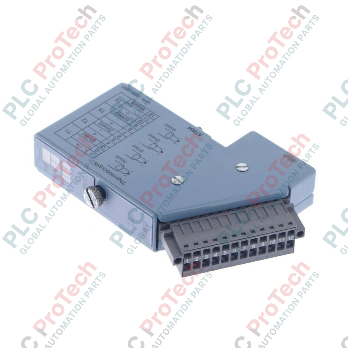
Le 7AT664.70 (7AT664.70) est un module d’entrée de température analogique 4 canaux à haute résolution développé par B&R Industrial Automation dans l’écosystème fiable de contrôle modulaire System 2003. Conçu comme un module à visser directement, ce bloc d’instrumentation offre des interfaces natives pour capteurs thermocouples, réalisant une acquisition de données de température haute précision sur des lignes de traitement industriel exigeantes. Dans des applications de traitement thermique telles que les cylindres de moulage par injection plastique, les fours de cuisson industriels, la fabrication de verre pharmaceutique et les autoclaves de stérilisation alimentaire, le 7AT664.70 garantit une stabilité thermique absolue et prévient les arrêts non planifiés grâce à un convertisseur analogique-numérique (CAN) avancé 16 bits et une isolation galvanique localisée canal-vers-bus. Sa conception mécanique robuste assure l’alignement des emplacements et la stabilité du bus de données malgré les vibrations continues de la machine.
Format matériel et topologie d’interface capteur
La configuration interne de ce module d’extension System 2003 est spécialement adaptée au traitement de signaux millivolts faibles et à la conversion déterministe des signaux :
-
Plan mécanique à visser : Conçu comme un module à visser standard System 2003, s’insérant directement dans le boîtier du contrôleur de base ou la base de bus E/S distribuée pour minimiser l’encombrement en profondeur du panneau.
-
Grille isolée 4 canaux : Dispose de 4 canaux d’entrée analogiques indépendants dédiés à la capture des différences de potentiel thermoélectrique au niveau microvolt sans interférence entre canaux.
-
Numérisation 16 bits : Convertit les faibles tensions des thermocouples en registres numériques à haute granularité, permettant au processeur principal de détecter en temps réel des variations de température infimes.
-
Compensation native de jonction froide : Intègre un suivi interne de la température de la jonction de référence pour compenser automatiquement les variations de température ambiante du bloc de connexion, garantissant une précision absolue des mesures.
Paramètres techniques essentiels
Le tableau suivant présente les paramètres mécaniques, électriques et de performance vérifiés pour l’intégration automatisée dans les panneaux de contrôle :
| Paramètre |
Spécifications |
| Modèle |
7AT664.70 |
| Marque |
B&R Industrial Automation |
| Origine |
Autriche |
| Classification du module |
Module d’extension à visser System 2003 |
| Nombre de canaux d’entrée |
4 canaux |
| Compatibilité capteurs |
Thermocouples industriels (interface millivolt directe) |
| Résolution du convertisseur A/N |
16 bits (configuration haute granularité) |
| Isolation galvanique |
Isolation canal-vers-bus arrière |
| Interface de connexion terrain |
Disposition intégrée du bloc de connexion |
| Plage de température de fonctionnement |
0 à 55 °C (tampon châssis standard) |
| Poids net du matériel |
0,35 kg |
| Poids d’expédition |
2,00 kg |
Base de connaissances techniques et questions fréquentes
Comment la résolution 16 bits du convertisseur améliore-t-elle le suivi de la température sur des thermocouples standards ?
Les capteurs thermocouples génèrent des pas de tension d’amplitude extrêmement faible, souvent de quelques microvolts ($ \mu\text{V} $) par degré de variation. En passant ces signaux à travers une matrice de conversion numérique à haute résolution 16 bits, le module divise la plage d’entrée analogique en $ 65\,536 $ pas numériques discrets. Cette résolution exceptionnelle permet au système de suivre des tendances de température subtiles et d’éviter les oscillations de suivi dans les boucles thermiques de précision.
Quels types d’erreurs de mise à la terre sont évités grâce à la conception isolée des canaux ?
Les thermocouples industriels sont souvent soudés ou fixés directement sur des composants métalliques de la machine (jonctions mises à la terre). Si plusieurs capteurs sont reliés à différentes zones d’un grand châssis, de légères différences de potentiel électrique entre ces points créent des courants de boucle de terre dangereux. La conception isolée des signaux du module interrompt ces chemins, bloquant le bruit électrique en mode commun qui pourrait corrompre le bus de données interne ou fausser les mesures de température.
Ce module peut-il être échangé à chaud pendant que la base System 2003 est en fonctionnement actif ?
Non. L’architecture de bus à visser System 2003 nécessite une coupure complète de l’alimentation logique avant l’insertion ou le retrait des modules. Retirer le module alors que le backplane est sous tension peut provoquer des micro-arcades entre les broches du bus, risquant une défaillance permanente des circuits logiques ou la corruption de l’image d’exécution du processeur actif.
Mise en service sur site et consignes de sécurité
-
Protocoles de câblage des rallonges thermocouples : Utilisez toujours un câble d’extension ou un fil compensateur dédié correspondant au type spécifique de capteur (par exemple, Type J, Type K) depuis la tête de sonde jusqu’au bloc de connexion. N’insérez jamais de fil cuivre standard dans la liaison intermédiaire, car le mélange de métaux crée des jonctions froides non intentionnelles qui provoquent de graves décalages dans le calcul de la température.
-
Blindage des signaux et séparation des interférences : Faites passer tous les fils thermocouples basse tension dans un conduit métallique dédié et mis à la terre ou dans un chemin de câbles séparé. Maintenez ces trajets sensibles aux millivolts éloignés d’au moins 200 mm des câbles d’alimentation AC à fort courant, des câbles moteurs et des sorties de variateurs de fréquence (VFD) pour supprimer complètement les interférences électromagnétiques haute fréquence.
-
Fixation des bornes et équilibre thermique : Dénudez proprement les extrémités des fils capteurs et serrez-les fermement dans le bloc de connexion. Évitez de monter la baie E/S directement à côté de sources de chaleur importantes comme les réacteurs de ligne ou les résistances de freinage dans le panneau de contrôle ; une chauffe localisée externe du bloc de connexion peut dégrader la précision du suivi de la compensation de jonction froide intégrée.