Capacités techniques et surveillance des processus
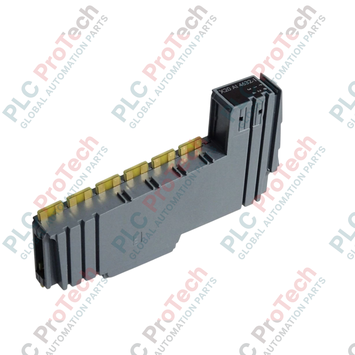
Le B&R X20AI4632-1 (X20AI4632-1) est un module d'entrée analogique différentiel 4 canaux haute performance conçu spécifiquement pour l'écosystème modulaire d'automatisation B&R X20. Utilisé dans des secteurs industriels exigeants tels que les usines de fusion métallurgique, les lignes de moulage par injection à cycle rapide et les machines synchronisées de papeterie, ce module capture des signaux de terrain à haute fréquence. En fournissant un suivi télémétrique précis ainsi que des fonctions avancées d'oscilloscope intégrées, l'unité permet aux ingénieurs de diagnostiquer les fluctuations transitoires des signaux directement depuis la couche de contrôle, réduisant ainsi le temps de diagnostic et évitant la dégradation coûteuse des équipements.
Conditionnement du signal et éléments de diagnostic
Ce module analogique avancé dispose de quatre entrées différentielles configurables indépendamment, capables de recevoir à la fois des signaux de tension dans une plage de ± 11 V et des boucles de courant allant de 0 à 22 mA. La sélection entre la réception de tension et de courant est gérée dynamiquement via des chemins distincts sur le bornier physique. La face avant intègre des groupes complets de LED de diagnostic qui indiquent en temps réel l'état des E/S par canal, l'état de fonctionnement et la santé globale du module. Le module consomme une puissance négligeable de 0,01 W sur le bus logique tout en utilisant 1,5 W sur l'alimentation interne des E/S pour alimenter ses circuits de filtrage.
Matrice de configuration physique
| Paramètre principal |
Spécification fonctionnelle |
| Modèle |
X20AI4632-1 |
| Marque |
B&R Automation |
| Origine |
Autriche |
| Variante de module |
Carte d'entrée analogique différentielle multifonction |
| Nombre de canaux |
4 entrées |
| Seuils de signal |
± 11 V ou 0 à 22 mA (déterminé par la connexion physique au bornier) |
| Schéma de connexion d'entrée |
Configuration d'entrée différentielle véritable |
| Fonctionnalité spécialisée |
Diagnostics d'oscilloscope haute vitesse intégrés |
| Consommation sur bus |
0,01 W |
| Consommation interne E/S |
1,5 W |
| Température de fonctionnement |
0 à 55 °C (montage horizontal standard) |
| Température de stockage |
-25 à 85 °C |
| Dimensions (L x H x P) |
12,5 x 99 x 74 mm |
| Poids net |
0,08 kg |
| Poids brut d'expédition |
1,0 kg (emballé dans un conditionnement rigide antistatique) |
Intégration système et FAQ
Comment basculer un canal de la lecture de tension à la surveillance de boucle de courant ?
Il n'y a pas d'utilisation de cavaliers matériels ni de variables logicielles pour ce changement. Le type de signal est entièrement déterminé par la manière dont le câblage de terrain est connecté sur le bornier X20. Le module utilise des broches de connexion différentes pour l'entrée de tension et pour l'entrée de courant. Consultez le schéma de câblage officiel B&R pour le X20AI4632-1 afin d'associer correctement votre transmetteur de terrain à la rangée de bornes appropriée.
Quels sont les avantages pratiques de la fonction oscilloscope intégrée ?
La fonction oscilloscope permet au module d'échantillonner des valeurs analogiques à grande vitesse et de stocker les données brutes dans un tampon interne. Ces données peuvent être consultées via B&R Automation Studio pour capturer des transitoires de signal ultra-rapides, des pics de tension ou des chutes de courant. Cette fonctionnalité permet aux techniciens de diagnostiquer des instruments de terrain défectueux sans avoir besoin de connecter des appareils de mesure externes physiques aux borniers actifs.
Quelle action doit être prise si la LED d'état du module devient rouge fixe ?
Une LED d'état rouge fixe indique une défaillance matérielle interne ou une incompatibilité de configuration entre le module physique et le projet logiciel. Vérifiez que le numéro de modèle correct (X20AI4632-1) est déclaré dans l'arborescence de configuration du contrôleur, inspectez la connexion du module à sa base de bus sous-jacente et assurez-vous que la tension d'alimentation interne des E/S est conforme aux tolérances standard.
Mise en service sur site et directives d'installation
-
Conformité du câblage des broches de bornier : Avant de connecter les fils, vérifiez le format de signalisation du transmetteur. Connecter une boucle de courant 20 mA sur une broche calibrée pour une entrée ± 11 V entraînera des calculs d'échelle incorrects et peut provoquer un stress thermique sur le réseau d'entrée interne. Vérifiez soigneusement toutes les positions des fils par rapport à l'étiquetage des bornes.
-
Atténuation du bruit différentiel : Utilisez toujours un câblage blindé à paires torsadées de haute qualité pour toutes les liaisons de capteurs différentiels. Connectez la tresse globale du câble directement à la barre de mise à la terre à faible impédance du bus X20. Maintenez ces chemins analogiques basse tension isolés des lignes moteurs triphasées et des contacteurs de commutation lourds d'au moins 200 mm afin de préserver l'intégrité des formes d'onde du signal.
-
Calcul de l'énergie potentielle du segment : Assurez-vous que la consommation interne de 1,5 W de ce module est entièrement prise en compte dans le budget énergétique du segment local du rack. Si la consommation cumulée des modules adjacents approche la limite maximale de l'alimentation actuelle, installez un module d'alimentation potentiel auxiliaire X20 directement à gauche de cette unité pour maintenir la stabilité de la tension.