Description technique et application
Le 8B0C0160HW00.001-1 (8B0C0160HW00.001-1) est un module d'alimentation auxiliaire industriel conçu pour une intégration directe au sein du système d'entraînement B&R ACOPOSmulti. Conçu pour fournir une alimentation stable aux composants électroniques internes dans des configurations complexes de contrôle de mouvement multi-axes — telles que celles rencontrées dans les lignes d'assemblage automobile, les presses d'impression automatisées et les machines d'emballage lourdes — ce module délivre une puissance continue de 400 W. Il garantit que les électroniques de contrôle critiques, les encodeurs et les réseaux de communication internes restent pleinement alimentés même en cas de fluctuations du bus DC principal ou de cycles de freinage régénératif soudains. L'intégration de ce matériel dans la chaîne d'entraînement optimise la régulation globale de la tension du système, protège les unités de traitement logique sensibles contre les baisses de tension et prévient les chutes d'axes non maîtrisées qui entraînent des arrêts coûteux sur le site de production.
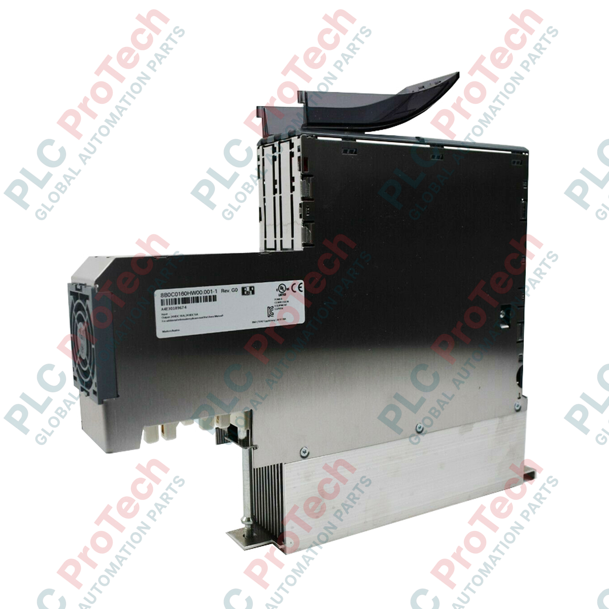
Architecture mécanique et dissipation thermique
Conçu avec un format vertical spécialisé pour s'adapter à la disposition modulaire compacte de la série ACOPOSmulti, le module présente des dimensions physiques approximatives de 26,3 cm x 5,3 cm x 31,7 cm. La largeur compacte de 5,3 cm permet aux ingénieurs d'insérer l'alimentation directement à côté des modules onduleurs sans augmenter l'encombrement de l'armoire électrique. Enveloppé dans un boîtier industriel robuste pesant 3,2 kg, l'unité utilise des voies de dissipation thermique passives et assistées par le système pour maintenir la sécurité opérationnelle sous charge continue. La conception mécanique comprend une connexion de montage sur backplane robuste, conçue pour résister aux vibrations mécaniques constantes et aux chocs industriels fréquents dans les centres de fabrication automatisés.
Spécifications de performance matérielle
| Paramètre |
Spécification technique |
| Modèle |
8B0C0160HW00.001-1 |
| Marque |
B&R (Bernecker + Rainer) |
| Type de module |
Module d'alimentation auxiliaire |
| Compatibilité système |
Infrastructure d'entraînement ACOPOSmulti |
| Puissance continue délivrée |
400 W |
| Profil de refroidissement |
Refroidissement par convection intégré à la chaîne |
| Dimensions (L x W x H) |
Environ 26,3 cm x 5,3 cm x 31,7 cm |
| Masse nette de l’unité |
3,2 kg |
| Masse brute pour expédition |
5,0 kg (emballé dans un conditionnement robuste multi-couches pour export) |
| Plage d’humidité de fonctionnement |
5 à 95 % sans condensation |
| Pays d’origine |
Autriche |
FAQ sur l’intégration système
Quelle est la fonction principale du 8B0C0160HW00.001-1 dans une chaîne d’onduleurs ACOPOSmulti ?
Le module sert de source dédiée de tension auxiliaire pour les cartes logiques de contrôle internes et les interfaces fieldbus des unités d’entraînement adjacentes. En séparant l’alimentation de contrôle des voies principales haute tension du moteur, il permet aux diagnostics et aux communications réseau de rester actifs même lorsque l’alimentation principale du moteur est isolée pour des raisons de sécurité.
Peut-on connecter plusieurs modules d’alimentation auxiliaire pour augmenter la puissance de sortie au-delà de 400 W ?
Les paramètres de distribution d’énergie doivent respecter les règles strictes d’empilage décrites dans le manuel d’ingénierie B&R ACOPOSmulti. Dépasser le seuil continu de 400 W sur un segment de bus unique nécessite de diviser correctement la chaîne d’entraînement en zones d’alimentation indépendantes plutôt que de câbler les sorties standard en parallèle.
Qu’est-ce qui provoque l’enregistrement d’une panne d’alimentation auxiliaire sur le contrôleur central ?
Un code de panne est généralement déclenché si la température interne du module dépasse les seuils sûrs du silicium ou si la tension de sortie chute en dessous de la limite nominale requise pour alimenter les cartes logiques internes. Ces états sont transmis via le bus central d’entraînement à B&R Automation Studio pour décodage diagnostique.
Mise en service sur site et protocoles de sécurité
-
Alignement des barres omnibus et couple de serrage : Lors du montage du module dans la ligne ACOPOSmulti, assurez-vous que les connecteurs à glissière des barres omnibus s’alignent parfaitement avec les modules adjacents. Serrez toutes les vis de fixation mécaniques et électriques aux couples exacts spécifiés dans la documentation système afin d’éviter une résistance ponctuelle élevée, qui peut générer des points chauds localisés et entraîner une défaillance prématurée.
-
Dégagement pour gestion thermique : Maintenez des zones de dégagement claires au-dessus et en dessous du boîtier du module pour permettre un flux d’air sans entrave à travers les canaux de refroidissement. L’accumulation de poussière ou les blocages à l’intérieur de l’armoire réduiront l’efficacité du circuit de puissance continue de 400 W, provoquant des arrêts de protection thermique.
-
Avertissement de sécurité pour décharge : Le module d’alimentation auxiliaire est directement connecté aux voies haute capacité du bus DC. Vérifiez toujours que la tension du bus DC principal du système est complètement dissipée (en utilisant un multimètre calibré aux points de test) avant d’effectuer des opérations d’extraction, d’insertion ou de câblage sur l’interface du module.