Description technique et application réseau
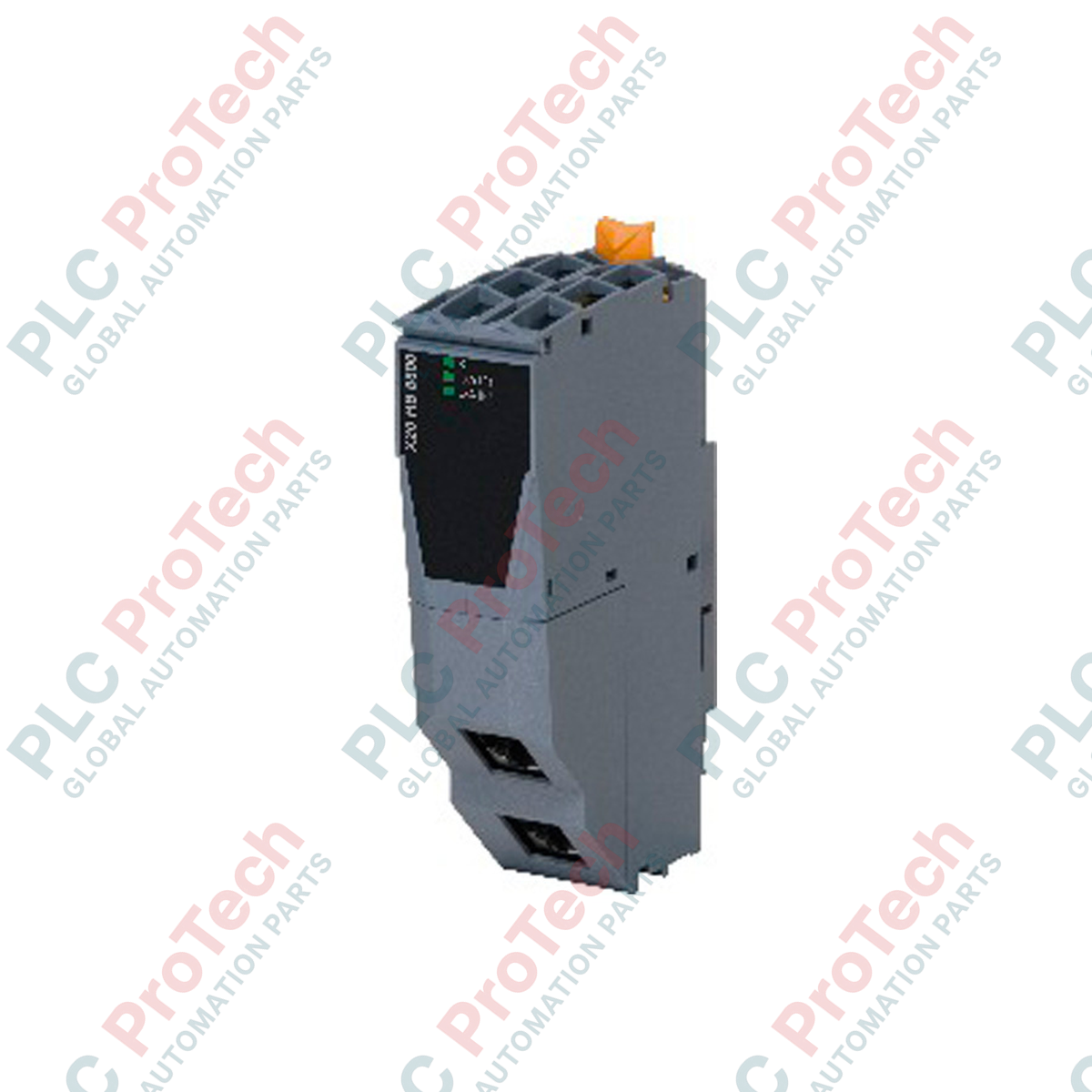
Le X20HB1881 (X20HB1881) est un module d’extension de concentrateur à fibre optique de qualité industrielle conçu pour la plateforme modulaire B&R X20 System. Conçu pour étendre la communication Ethernet à haute vitesse sur de longues distances physiques, ce module excelle dans les environnements de traitement décentralisé tels que les stations d’épuration, les centres de fabrication multi-bâtiments et les exploitations minières à ciel ouvert. Il intègre une interface concentrateur 100 BASE-FX conçue pour le câblage à fibre optique multimode, offrant une portée de transmission opérationnelle allant jusqu’à 2 km sans dégradation du signal. En convertissant les signaux électriques du bus en signaux optiques, le module assure une isolation électrique complète entre l’alimentation et le réseau Ethernet. Ce choix de conception protège l’infrastructure d’automatisation centrale des courants de boucle de masse, des surtensions haute tension et des interférences électromagnétiques sévères (EMI).
Architecture réseau et logique d’interface
Fonctionnant à un débit de transfert de données déterministe de 100 Mbit/s, ce module dispose d’une interface physique équipée d’un connecteur duplex LC femelle pour un alignement stable de la fibre optique. Le matériel du module prend en charge la fonctionnalité de remplacement à chaud complet, permettant au personnel de maintenance de remplacer le composant pendant le fonctionnement actif du système sans interrompre le lien de communication des tranches d’E/S adjacentes. Les diagnostics embarqués comprennent des voyants LED clairs qui affichent des mises à jour en temps réel sur l’état général du module et la fonction du bus active. Conçu pour un fonctionnement à faible signature thermique, le module consomme une puissance maximale de 1,45 W (les révisions antérieures à DO consomment jusqu’à 1,65 W) depuis le bus du châssis système, maintenant une faible accumulation de chaleur interne dans le rack d’assemblage.
Performances et spécifications réseau
| Paramètre |
Spécification technique |
| Modèle |
X20HB1881 |
| Marque |
B&R (Bernecker + Rainer) |
| Catégorie de module |
Concentrateur de communication X20 System |
| Port d’interface |
1x concentrateur 100 BASE-FX |
| Variante de connecteur |
1x duplex LC femelle |
| Type de média |
Câble à fibre optique multimode |
| Distance maximale de transmission |
Jusqu’à 2 km |
| Vitesse de transfert de données |
100 Mbit/s |
| Isolation électrique |
Réseau Ethernet isolé de l’alimentation |
| Support du remplacement à chaud |
Oui (remplacement à chaud complet) |
| Dissipation de puissance |
Max. 1,45 W (révisions antérieures à DO : max. 1,65 W) |
| Diagnostics matériels |
LED embarquées pour état du module et fonction du bus |
| Pays d’origine |
Autriche |
| Poids brut à l’expédition |
1,5 kg (enveloppé dans une protection anti-décharge électrostatique) |
FAQ sur l’intégration technique
Quels sont les avantages spécifiques de l’utilisation de la fibre optique X20HB1881 par rapport aux modules RJ45 cuivre standard ?
Les câbles Ethernet cuivre standard sont limités à des longueurs de 100 mètres et sont sensibles au bruit électromagnétique généré par les variateurs de fréquence haute puissance (VFD) et les machines lourdes. Le X20HB1881 utilise de la fibre multimode, étendant la portée du réseau jusqu’à 2 km tout en restant totalement immunisé contre les EMI industrielles, les diaphonies et les surtensions induites par la foudre.
Le remplacement à chaud du X20HB1881 interrompt-il le réseau de communication des autres modules ?
Non. L’architecture du backplane X20 permet d’extraire et d’insérer le X20HB1881 pendant que le reste du rack reste sous tension. Cependant, toute communication de données optiques active passant directement par ce module spécifique sera interrompue jusqu’à ce que la carte de remplacement soit insérée et initialisée.
Ce module peut-il être utilisé avec des câbles à fibre optique monomode ?
Non. Le transceiver optique à l’intérieur du X20HB1881 est réglé exclusivement pour les caractéristiques d’onde et les diamètres de cœur des câbles à fibre optique multimode. Forcer une connexion avec de la fibre monomode entraînera une forte atténuation optique et une défaillance de communication.
Mise en service sur site et directives optoélectroniques
-
Protection et propreté de l’interface optique : Les particules de poussière en suspension dans l’air et les huiles des doigts peuvent obstruer les petites ouvertures optiques du connecteur duplex LC. Gardez les capuchons en caoutchouc protecteurs installés en permanence jusqu’à ce que les câbles de terrain soient prêts pour l’insertion finale. Nettoyez les embouts de la fibre avec un outil industriel de nettoyage de fibre optique désigné avant l’insertion.
-
Limites du rayon de courbure de la fibre optique : Lors du routage des câbles à fibre optique multimode à l’intérieur de l’armoire électrique, respectez strictement le rayon de courbure minimum spécifié par le fabricant (généralement au moins 20 fois le diamètre du câble sous tension). Les courbures brusques provoquent des microfissures dans le cœur en verre, entraînant une forte perte de signal et des pertes intermittentes de paquets.
-
Insertion et alignement dans le backplane : Lors de l’utilisation de la fonction de remplacement à chaud, insérez le module en douceur dans le bloc terminal de base X20. Assurez-vous que les clips de verrouillage intégrés s’enclenchent solidement sur le rail pour éviter que les vibrations mécaniques ne déplacent le transceiver optique par rapport à la connexion du backplane.