Présentation du produit
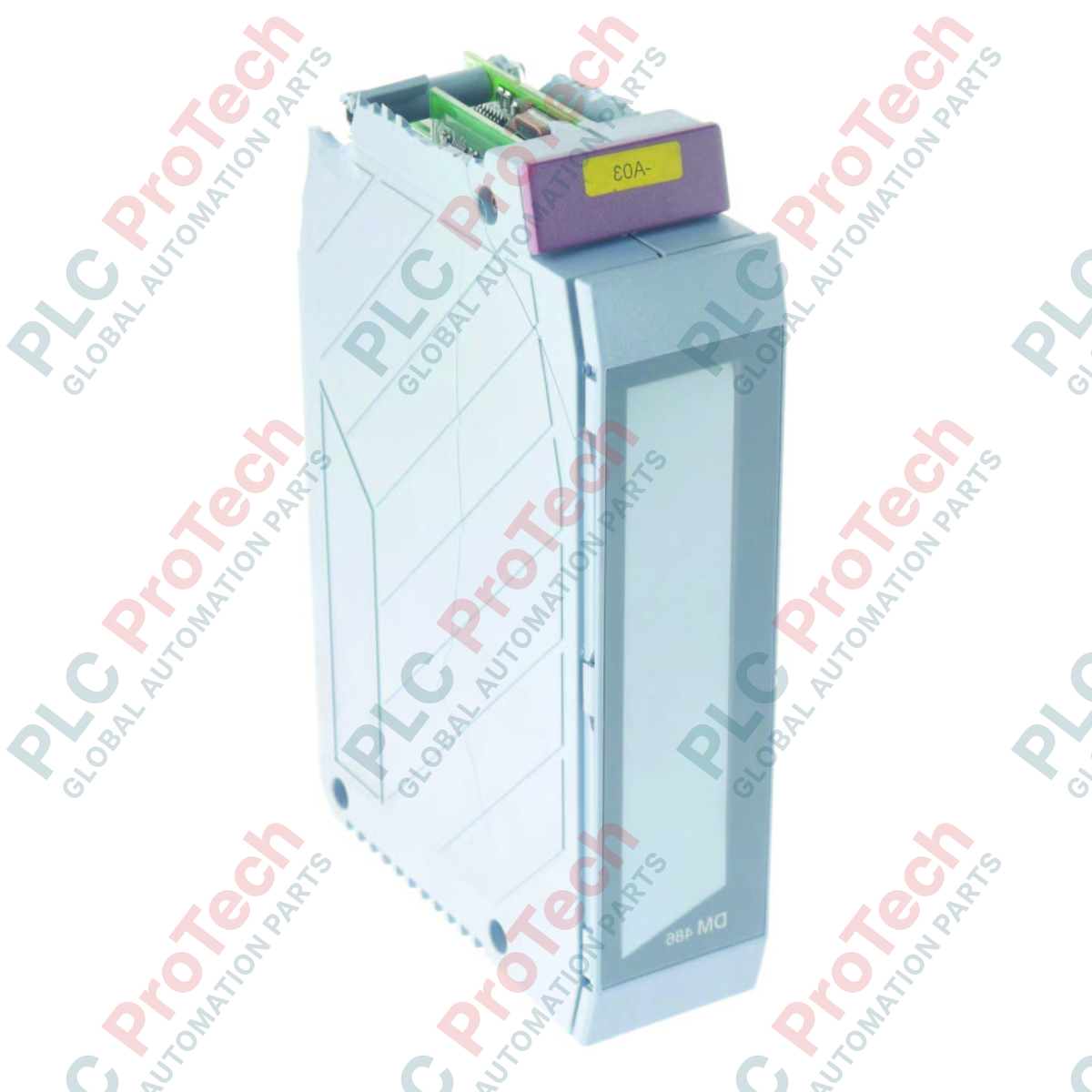
Le 3DM486.6 (3DM486.6) est un module d’E/S mixtes numériques polyvalent de la série B&R DM486, conçu pour offrir une intégration flexible des signaux dans les systèmes de contrôle automatisés. Combinant à la fois des fonctions d’entrée et de sortie dans une seule unité, ce module constitue une solution efficace pour les machines et les panneaux de commande nécessitant un équilibre entre la surveillance des signaux numériques et le contrôle des actionneurs. Le 3DM486.6 est conçu pour maintenir un haut niveau d’intégrité des signaux et un fonctionnement fiable en environnements industriels, garantissant une communication fluide entre capteurs, dispositifs de terrain et système de contrôle central.
Configuration technique
Ce module mixte est optimisé pour les applications où l’espace et l’efficacité du câblage sont essentiels, offrant une architecture robuste pour la gestion des signaux numériques.
-
Flexibilité des signaux mixtes : Combine plusieurs entrées et sorties numériques dans un seul module, simplifiant le nombre d’E/S par emplacement et réduisant l’encombrement matériel global de l’assemblage de contrôle.
-
Gestion de l’alimentation : Le module est conçu pour une alimentation externe 24 VDC, avec une consommation interne optimisée à 1,2 W (5 VDC) afin de minimiser l’impact thermique dans l’armoire de commande.
-
Isolation par groupe : Intègre une isolation électrique par groupes entre les groupes d’entrées et entre les groupes d’entrées/sorties, améliorant significativement la stabilité du système en réduisant les risques de diaphonie et de défauts liés aux potentiels.
-
Fiabilité du système : Conforme à la norme de protection IP20, le module est résistant aux débris, ce qui le rend idéal pour une installation dans des armoires électriques standard.
Caractéristiques techniques
| Attribut |
Spécifications |
| Modèle |
3DM486.6 |
| Marque |
B&R Automation |
| Série |
DM486 |
| Type de module |
E/S numériques mixtes |
| Configuration des signaux |
16 entrées/sorties numériques |
| Tension nominale |
24 VDC |
| Consommation électrique |
2,2 W (externe) / 1,2 W (interne) |
| Isolation électrique |
Isolation par groupe (Entrée-Entrée, Entrée-Sortie) |
| Indice de protection |
IP20 |
| Poids à l’expédition |
2 kg |
FAQ sur le matériel industriel
Quel est l’avantage de l’isolation par groupe dans ce module ?
La fonction d’isolation par groupe assure une séparation électrique entre différentes banques de signaux (Entrée-Entrée et Entrée-Sortie). Cette architecture empêche les surtensions ou les parasites de masse provenant d’un groupe d’affecter les performances des autres, ce qui est essentiel pour éviter des défauts à l’échelle du système dans des environnements de contrôle complexes.
Ce module convient-il aux applications de commutation à haute vitesse ?
Le 3DM486.6 est conçu pour des tâches standard d’E/S numériques industrielles. Bien qu’il offre une excellente fiabilité pour les signaux d’automatisation typiques, vérifiez toujours les temps de réponse spécifiques et les limites de fréquence dans le manuel technique B&R si votre application implique des impulsions à haute vitesse ou des retours de contrôle de mouvement critiques.
Ce module nécessite-t-il une orientation de montage spécifique ?
Comme la plupart des modules numériques standard B&R, le 3DM486.6 est conçu pour une installation dans des armoires de commande standard. Assurez une ventilation adéquate autour du module pour maintenir la chaleur générée par la charge externe de 2,2 W dans les limites de fonctionnement spécifiées pour l’armoire.
Mise en service sur site et consignes de sécurité
Mise à la terre et référence de potentiel
Bien que le module dispose d’une isolation par groupe, il est impératif d’établir une référence de masse commune solide pour votre système de contrôle. Assurez-vous que l’alimentation 24 VDC est correctement référencée et que tous les blindages de signaux sont terminés sur le bus de terre principal de l’armoire afin de préserver l’intégrité des barrières d’isolation.
Bonnes pratiques de câblage
Pour garantir une fiabilité à long terme, utilisez un câblage avec embouts à fourche appropriés pour toutes les connexions d’E/S. Lors du routage des câbles de signal, maintenez une séparation physique d’au moins 200 mm par rapport aux câbles d’alimentation à fort courant, aux lignes d’alimentation des moteurs AC ou aux sorties des variateurs de fréquence afin d’éviter les interférences électromagnétiques induites.
Vérification diagnostique
Lors de la mise en service initiale, vérifiez les états des signaux à l’aide des outils de diagnostic logiciel B&R. La nature modulaire de la série DM486 permet des contrôles rapides de l’état ; si un canal ne bascule pas, vérifiez la tension d’alimentation 24 VDC au niveau du bornier avant d’inspecter le câblage du dispositif de terrain ou du capteur.