Présentation de l’architecture réseau
Le B&R X20BM05 (X20BM05) est un module de bus de base matériel hautement spécialisé conçu pour l’écosystème d’automatisation modulaire B&R X20. Utilisé dans des installations de production multi-nœuds complexes, des usines de traitement chimique et des topologies de contrôle maritime distribuées, ce module de bus sert de fondation structurelle et électrique pour tous les modules d’alimentation X20. En intégrant directement des commutateurs de numéro de nœud physiques dans la base du backplane, l’unité dissocie l’identification de l’adresse du nœud des modules électroniques échangeables à chaud. Cette conception garantit une cartographie cohérente des dispositifs réseau, simplifie la séquence de maintenance et évite les erreurs de configuration lors des remplacements de composants.
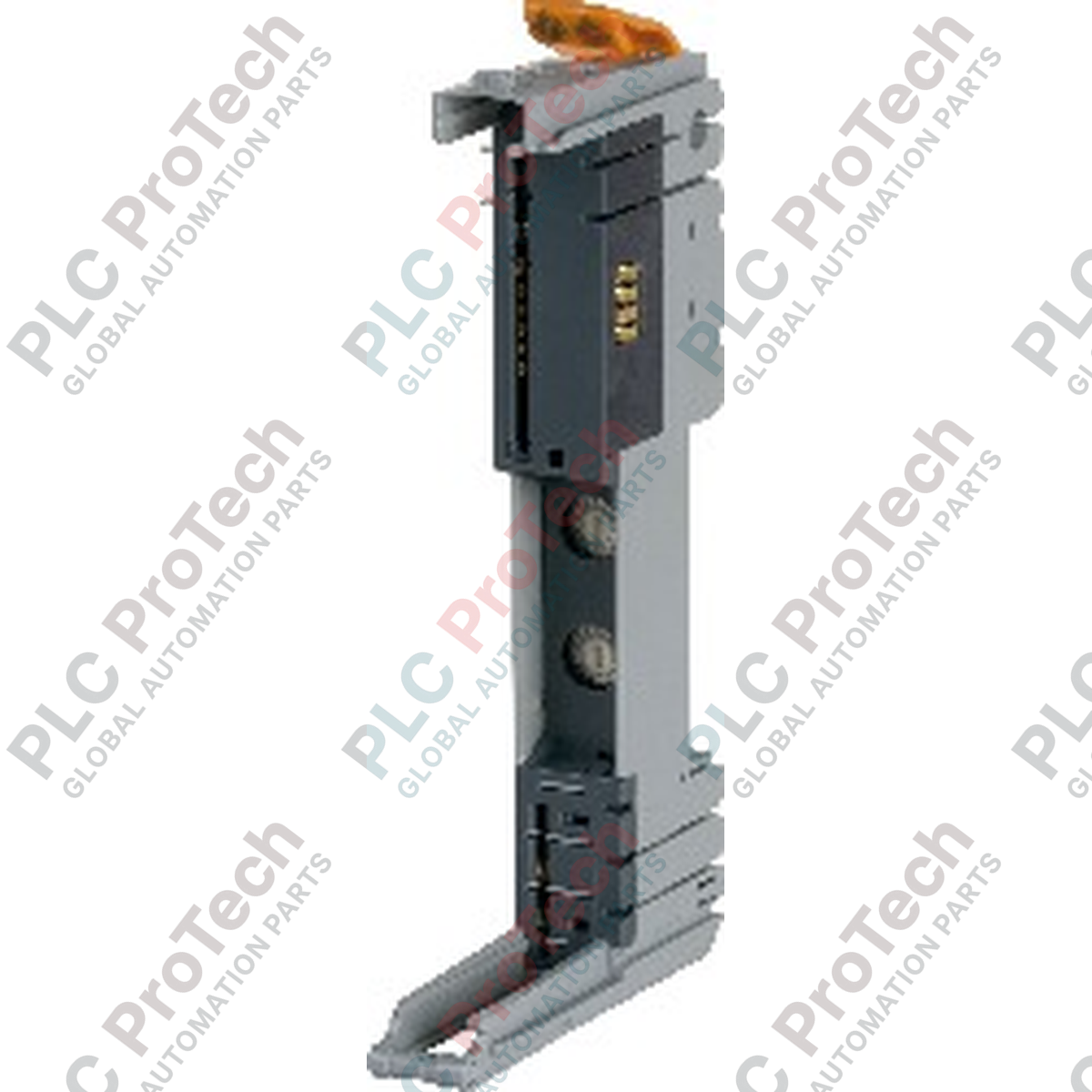
Isolation des segments et capacités d’adressage
Le X20BM05 est conçu pour établir des groupes de tension isolés au sein d’une armoire d’E/S standard. Sa principale caractéristique électrique est une barrière d’interruption physique qui isole les lignes d’alimentation interne des E/S à gauche du module. Cette disposition permet aux ingénieurs de diviser une armoire physique unique en segments de potentiel distincts et indépendants pour gérer en toute sécurité des boucles d’arrêt d’urgence ou des groupes d’instruments de terrain séparés. Le module comprend deux commutateurs rotatifs intégrés pour l’attribution manuelle du numéro de nœud décimal, qui peuvent être combinés de manière transparente avec les paramètres d’adressage automatique dans B&R Automation Studio.
Matrice de performance technique
| Paramètre matériel |
Spécification opérationnelle |
| Modèle |
X20BM05 |
| Marque |
B&R Automation |
| Origine |
Autriche |
| Classification du module |
Module de bus de base d’alimentation |
| Clé matérielle |
Clé mécanique 24 VDC |
| Limite de segment de bus |
Alimentation interne des E/S isolée à gauche |
| Topologie d’adressage |
Attribution manuelle du numéro de nœud via commutateurs matériels |
| Profil de tension nominale |
24 VDC |
| Charge de contact admissible |
Capacité maximale du backplane de 10 A |
| Consommation électrique interne du bus |
0,13 W |
| Largeur du module (pas) |
12,5 mm (+0,2 mm de tolérance de fabrication) |
| Limites de température horizontale |
-25 à 60 °C |
| Limites de température verticale |
-25 à 50 °C |
| Contraintes d’humidité |
5 à 95 % d’humidité relative (sans condensation) |
| Poids structurel net |
0,05 kg |
| Poids brut d’expédition |
2,0 kg (emballage rigide de transport inclus) |
Intégration système et FAQ
Quel est l’objectif fonctionnel de l’isolation de l’alimentation interne des E/S à gauche ?
La conception d’isolation empêche la tension 24 VDC de traverser les lignes du backplane vers les modules montés immédiatement à gauche du X20BM05. Cette fonctionnalité crée une zone de tension distincte, permettant aux équipes de maintenance d’isoler, de couper l’alimentation ou de modifier les dispositifs de terrain à droite de l’armoire sans interrompre l’alimentation électrique des équipements configurés à gauche.
Comment l’altitude affecte-t-elle le profil thermique de fonctionnement de ce module de bus ?
Pour des installations situées entre 0 et 2000 mètres d’altitude, le module fonctionne normalement sans restrictions environnementales. Pour des emplacements au-dessus de 2000 mètres, la raréfaction de l’air réduit la dissipation naturelle de la chaleur ; par conséquent, la température ambiante maximale admissible doit être réduite de 0,5 °C pour chaque 100 mètres d’altitude supplémentaire.
Peut-on remplacer un module électronique pendant que les commutateurs d’adresse du système sont ajustés ?
Oui. Comme les commutateurs rotatifs d’adresse sont situés directement sur la base matérielle X20BM05 et non sur le module électronique enfichable, l’ID réseau du nœud actif reste fixé à la position spécifique sur le rail DIN. En cas de défaillance électronique, le module de traitement supérieur peut être remplacé tout en conservant l’adresse physique intacte.
Directives de mise en service et d’installation sur site
-
Alignement de l’adressage des commutateurs de nœud : Réglez les deux commutateurs rotatifs décimaux à l’aide d’un petit tournevis plat avant de clipser le module électronique supérieur en place. Assurez-vous que les cadrans des dizaines et des unités reflètent précisément l’adresse de nœud spécifique attribuée dans l’arborescence de configuration matérielle du contrôleur maître pour éviter les conflits d’adresses sur le réseau de terrain.
-
Gestion du courant du backplane : Veillez à ce que la consommation cumulée de courant de toutes les cartes d’E/S en aval alimentées dans cette zone de potentiel ne dépasse pas la limite stricte de charge de contact admissible de 10 A. Dépasser ce seuil entraînera une dégradation thermique prématurée des clips de bus plaqués or internes et provoquera des défaillances intermittentes du bus.
-
Tolérances de montage sur rail DIN : Lors de l’assemblage de plusieurs modules, maintenez un plan de montage stable. Le pas structurel de 12,5 mm repose sur un alignement parfaitement perpendiculaire sur des rails DIN TS35 standard. Assurez-vous que le rail est propre et exempt de déformations, et installez des butées mécaniques robustes aux deux extrémités de l’ensemble fini pour éviter la séparation latérale des modules.