Vue d'ensemble de la surveillance des processus
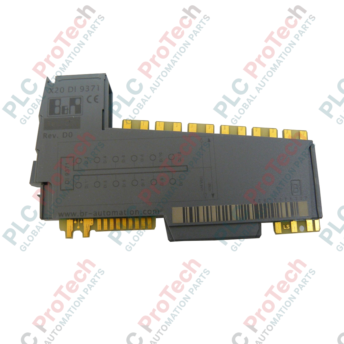
Le B&R X20DI9371 (X20DI9371) est un module d'interface capteur discret haute densité à 12 canaux conçu pour la plateforme de contrôle modulaire B&R X20. Fonctionnant au sein de réseaux d'automatisation à haut débit tels que les lignes de prélèvement automatisées, les presses à emboutir métalliques et les lignes de transformation alimentaire continues, ce module capture les changements d'état au niveau terrain. En traitant la télémétrie en temps réel provenant des capteurs de proximité, des interrupteurs de sécurité et des boutons-poussoirs, l'unité assure une transmission réactive des signaux vers le processeur central, minimisant la latence de la boucle de contrôle et évitant les erreurs de synchronisation des séquences.
Architecture du circuit et dynamique des filtres
Ce module numérique dispose de 12 canaux d'entrée configurés pour des topologies de connexion 1-fil économes en espace. Conçu avec une configuration de circuit d'entrée en mode sink (NPN) conforme aux normes EN 61131-2 Type 1, chaque canal présente une résistance d'entrée typique de 6,4 kΩ et consomme 3,75 mA sous une tension nominale de 24 VDC. Pour supprimer les rebonds de contact électrique et les bruits inductifs en atelier, le module intègre un système de filtrage à deux étages : un filtre matériel ultra-rapide fonctionnant à ≤100 μs combiné à un filtre logiciel réglable de 0 à 25 ms par pas précis de 0,2 ms.
Matrice de performance technique
| Paramètre principal |
Spécification opérationnelle |
| Modèle |
X20DI9371 |
| Marque |
B&R Automation |
| Origine |
Autriche |
| Densité d'entrée |
12 entrées digitales |
| Configuration du circuit |
Sink (configuration NPN) |
| Conception du câblage |
Topologie de connexion 1-fil |
| Classification standard |
Caractéristiques EN 61131-2 Type 1 |
| Tension d'entrée nominale |
24 VDC (plage de fonctionnement -15% / +20%) |
| Courant d'entrée (à 24 VDC) |
Typ. 3,75 mA par canal |
| Résistance d'entrée |
Typ. 6,4 kΩ |
| Intervalle du filtre matériel |
≤100 μs |
| Plage du filtre logiciel |
0 à 25 ms (réglage par défaut 1 ms) |
| Consommation d'énergie du bus |
0,18 W |
| Consommation interne I/O |
1,75 W |
| Poids |
0,08 kg (net) / 2,0 kg (brut avec emballage) |
Maintenance industrielle et FAQ
Comment réinitialiser un canal qui affiche des transitions faussement positives dans un environnement à fort bruit électromagnétique ?
Accédez à la fenêtre de configuration I/O du module dans B&R Automation Studio. Augmentez le temps du filtre logiciel par défaut de 1 ms par incréments de 0,2 ms (jusqu'à 25 ms) pour masquer les pics de tension induits à haute fréquence. Si les déclenchements erronés persistent, inspectez le cheminement physique du câble du capteur et vérifiez que l'interrupteur de proximité correspond aux exigences de l'interface sink 6,4 kΩ.
Un capteur standard sourcing (PNP) à 3 fils peut-il être connecté directement à ce module d'entrée ?
Non. Le X20DI9371 utilise une configuration sink, ce qui signifie que la borne d'entrée nécessite que le dispositif terrain commute le côté négatif (0 VDC) du circuit pour enregistrer un état actif. Connecter directement un capteur PNP standard (qui fournit 24 VDC) ne complétera pas le chemin du circuit. Utilisez un capteur NPN ou installez un relais d'interposition externe pour inverser le signal.
Un câblage d'alimentation séparé est-il nécessaire pour les topologies de connexion 1-fil ?
Oui. Parce qu'une connexion 1-fil signifie que seul le fil de signal actif revient directement au bornier du module, les capteurs externes doivent recevoir leur alimentation 24 VDC depuis un bloc de distribution de potentiel séparé, tel qu'une carte de distribution de potentiel X20PD située dans le même segment de rack.
Mise en service sur site et consignes de câblage
-
Suivi du potentiel de référence commun : Assurez-vous que l'alimentation externe 24 VDC alimentant les capteurs terrain partage une masse de référence 0 VDC commune avec le rack X20. Sans référence de masse unifiée, les entrées sink NPN ne peuvent pas former un chemin électrique complet à travers la résistance interne de 6,4 kΩ, ce qui entraîne des états de signal erratiques ou une défaillance complète de l'entrée.
-
Isolation des signaux à haute vitesse : Lors de l'utilisation des propriétés du filtre matériel rapide (≤100 μs), blindez tous les fils d'impulsions entrants. Éloignez complètement ces lignes de signal discrètes des câbles d'alimentation triphasés puissants et des câbles de sortie de variateurs de fréquence pour éviter les diaphonies générant des comptages d'état erronés.
-
Contraintes d'installation du module sur rail DIN : Intégrez le profil de puissance combiné — spécifiquement la consommation de bus de 0,18 W et la charge interne I/O de 1,75 W — dans le calcul thermique total du segment de bus local. Avant de verrouiller le module sur le rail DIN, vérifiez que les onglets d'alignement de la base correspondent précisément aux modules adjacents pour éviter la déformation des broches sur le bus interne du backplane.