Description fonctionnelle du système
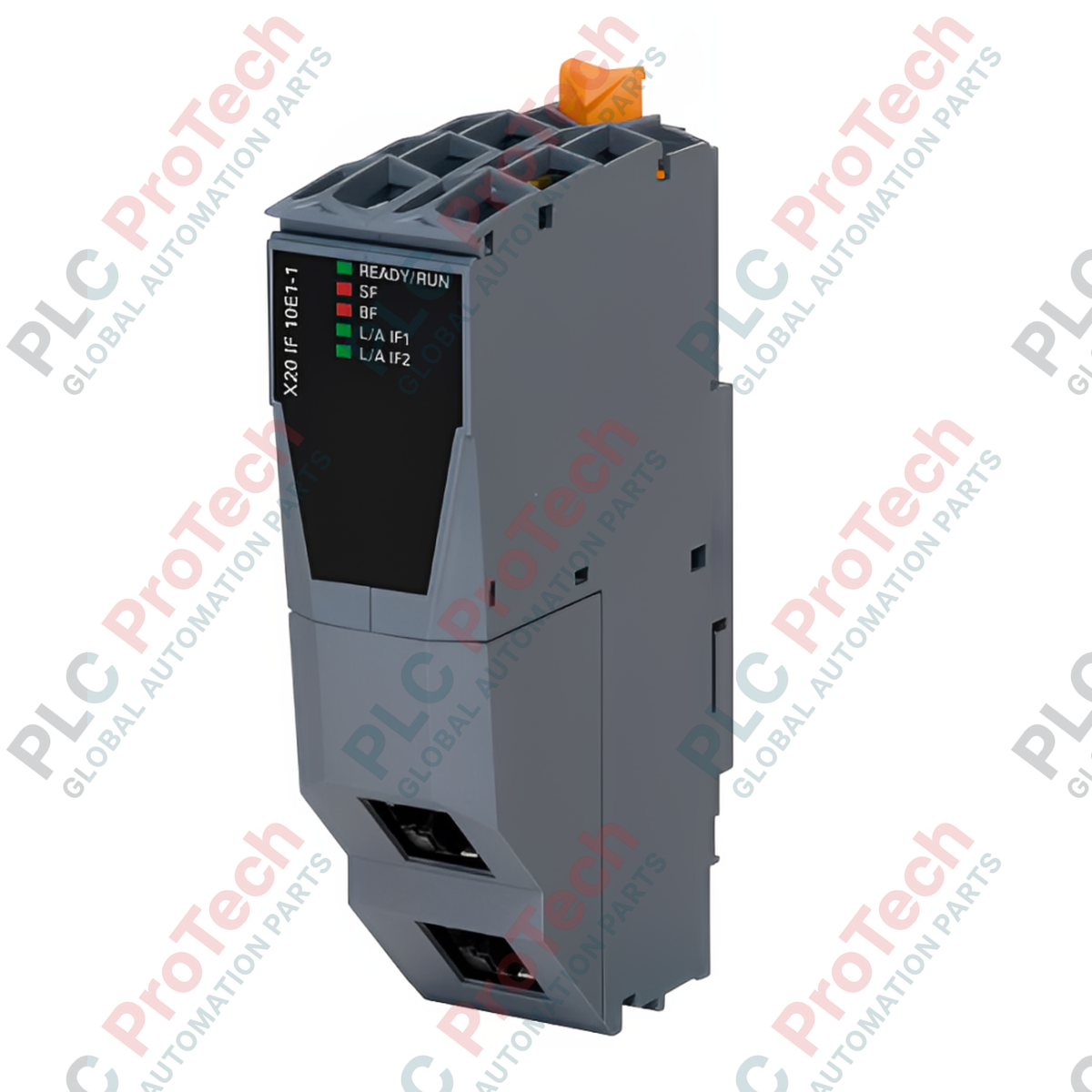
Le B&R X20IF10E1-1 (X20IF10E1-1) est un module d’interface contrôleur PROFINET IO haute performance conçu pour une intégration transparente dans l’architecture standard du système B&R X20. Déployé mondialement dans des applications industrielles complexes telles que les lignes d’assemblage automobile, les réseaux d’emballage à grande vitesse et les installations municipales de traitement de l’eau, ce module établit une connectivité maître Ethernet en temps réel déterministe. En déchargeant le traitement du bus de terrain du CPU principal, il minimise les temps de cycle de boucle et garantit un débit de données rapide, réduisant significativement la latence système et évitant les goulets d’étranglement coûteux dans les lignes d’automatisation synchronisées.
Architecture du bus de terrain et dynamique de transmission
Conçu comme un maître PROFINET IO dédié, ce module dispose d’une variante à double port RJ45 blindée avec un commutateur intégré pour faciliter des topologies réseau en ligne ou en anneau flexibles sans nécessiter de commutateurs industriels externes. Le matériel supporte des débits standard de 100 Mbit/s sur une longueur maximale de segment de 100 m entre stations. Pour protéger les unités de traitement internes sensibles contre les transitoires haute tension sur le site industriel, le module d’interface intègre une isolation électrique complète entre le backplane principal du PLC et les canaux PROFINET IO (IF1 et IF2).
Matrice de performance technique
| Caractéristique |
Spécification |
| Modèle |
X20IF10E1-1 |
| Marque |
B&R (Architecture Automation Studio) |
| Origine |
Autriche |
| Type d’interface |
Contrôleur PROFINET IO (Maître) |
| Interface physique |
2x RJ45 blindés (Commutateur intégré) |
| Vitesse de transmission |
100 Mbit/s |
| Distance maximale de segment |
100 m entre deux stations |
| Isolation galvanique |
Logique PLC entièrement isolée de IF1 et IF2 |
| Consommation électrique |
2 W |
| Température de fonctionnement |
0 à 55 °C (Montage horizontal standard) |
| Dimensions (L x H x P) |
25 x 99 x 74 mm |
| Poids |
0,12 kg (Net) / 2,0 kg (Brut avec emballage) |
FAQ techniques
Le commutateur intégré sur le X20IF10E1-1 supporte-t-il le protocole de redondance média PROFINET (MRP) ?
Oui. La configuration du commutateur RJ45 blindé à double port permet au module de fonctionner dans une topologie en anneau régie par les paramètres PROFINET MRP. Cette configuration garantit qu’en cas de rupture d’un câble réseau, la communication se rétablit en quelques millisecondes pour maintenir une opération continue de l’usine.
Quelle action doit être prise si le module ne parvient pas à établir un lien avec un nœud esclave sur une distance de 90 mètres ?
Vérifiez d’abord l’intégrité des connexions RJ45 blindées et assurez-vous d’utiliser un câblage Ethernet industriel de catégorie Cat 5e ou supérieure. Assurez-vous que la longueur totale ne dépasse pas la limite stricte de 100 m par segment, et vérifiez que les blindages des câbles sont correctement mis à la terre aux deux extrémités pour éliminer les interférences électromagnétiques importantes.
Un câblage d’alimentation externe séparé est-il nécessaire pour atteindre la consommation de 2 W ?
Non. Le X20IF10E1-1 puise ses 2 W de puissance de fonctionnement directement sur le bus interne du backplane du système X20. Cependant, les intégrateurs doivent calculer le budget total de puissance du rack pour s’assurer que le module d’alimentation principal du système X20 dispose d’une capacité suffisante.
Mise en service sur site et consignes de sécurité
-
Cadre de blindage et de mise à la terre : Lors du raccordement des câbles de communication aux ports RJ45 doubles, utilisez toujours des connecteurs RJ45 industriels entièrement blindés avec boîtiers métalliques. Le blindage du câble doit être en contact direct avec le boîtier du port. Cette disposition maintient la barrière d’isolation électrique entre le réseau industriel et les rails logiques internes du PLC, déviant les surtensions transitoires loin du processeur.
-
Chemins de câblage réseau : Maintenez une séparation physique entre les lignes Ethernet PROFINET et les câbles d’alimentation AC haute tension ou les câbles de sortie des variateurs de fréquence (VFD). Croisez ces câbles à angle droit plutôt que de les faire courir parallèlement pour éviter que le couplage des champs magnétiques ne corrompe les paquets de données à 100 Mbit/s.
-
Insertion du module et alignement sur le backplane : Assurez-vous que le module de base X20 est solidement verrouillé sur le rail DIN avant d’insérer le module électronique X20IF10E1-1. Inspectez les connecteurs dorés du bus backplane pour détecter toute saleté avant l’insertion afin d’éviter des contacts à haute résistance pouvant entraîner des coupures intermittentes de l’alimentation 2 W ou des erreurs de communication sur le bus.