Présentation de l'automatisation des processus
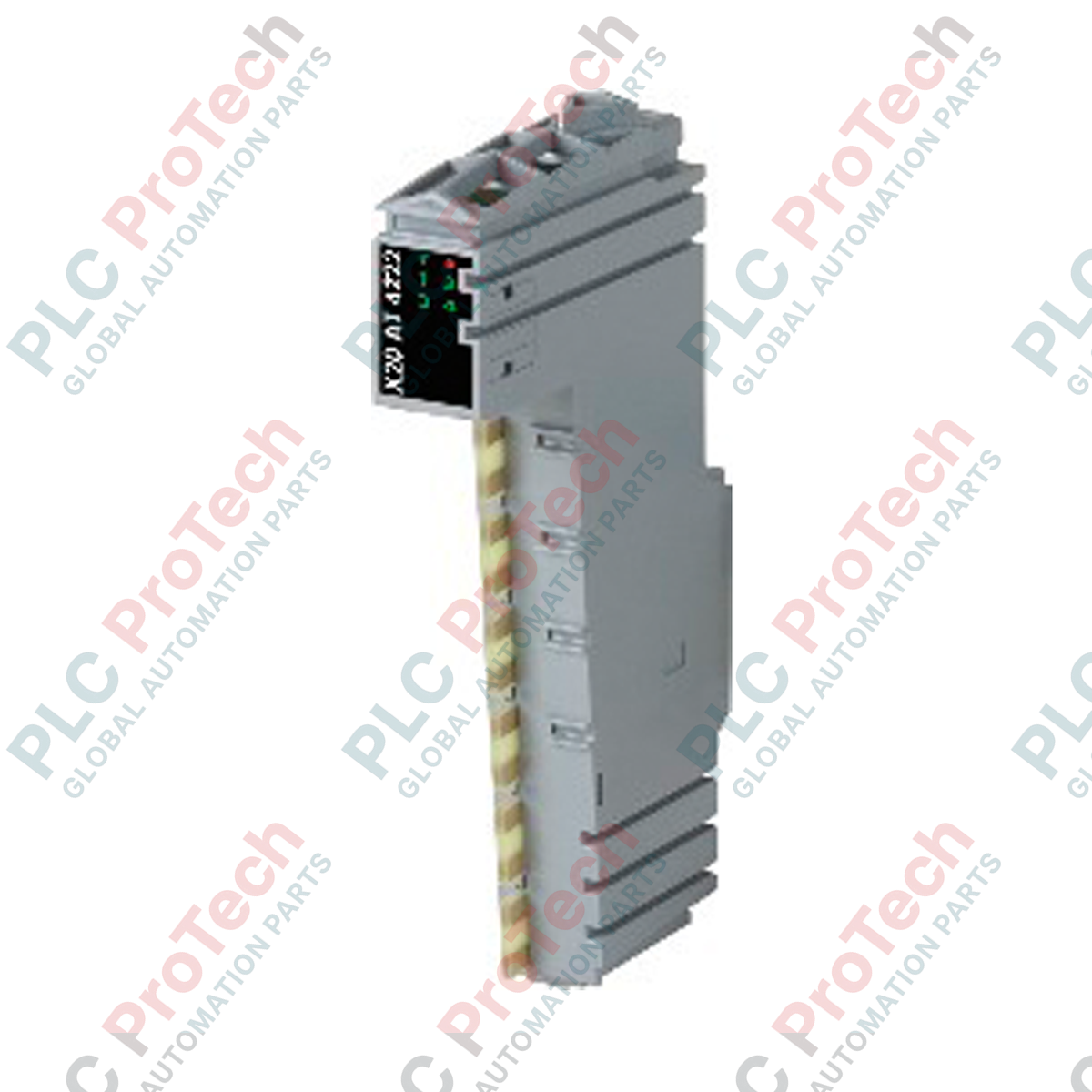
Le B&R X20AT4222 (X20AT4222) est un module d'entrée de mesure de température par résistance à 4 canaux haute précision, conçu pour une intégration dans l'environnement modulaire de contrôle B&R X20. Utilisé dans des industries thermiques exigeantes telles que la fabrication chimique, l'extrusion de plastique et la validation climatique pharmaceutique, ce module se connecte directement aux capteurs RTD standards pour stabiliser les processus thermiques en boucle fermée. En transmettant des mesures de température précises directement au contrôleur centralisé, l'unité élimine les fluctuations de traitement et protège les équipements contre les dépassements thermiques, réduisant ainsi les pertes matérielles coûteuses et maximisant la disponibilité du processus.
Architecture de conversion et interfaces capteurs
Équipé de quatre entrées analogiques optimisées pour les détecteurs de température à résistance Pt100 et Pt1000, le module utilise une architecture de convertisseur Sigma-delta haute efficacité avec une résolution numérique de 16 bits. Il prend en charge nativement les installations en 2 fils et 3 fils, utilisant une alimentation en courant constant intégrée pour compenser la résistance intrinsèque des lignes sur de longues distances de câble. Le système dispose d'un filtre matériel configurable avec des paramètres de temps ajustables de 1 ms à 66,7 ms, permettant aux ingénieurs d'éliminer les bruits électriques haute fréquence provenant des équipements environnants.
Matrice de performance technique
| Métrique |
Spécification |
| Modèle |
X20AT4222 |
| Marque |
B&R Automation |
| Origine |
Autriche |
| Canaux d'entrée |
4 entrées pour RTD Pt100 ou Pt1000 |
| Configuration de connexion |
Infrastructure 2 fils ou 3 fils |
| Type de convertisseur |
Sigma-delta 16 bits |
| Résolution de mesure |
0,1 °C |
| Intervalles de filtrage |
Configurable de 1 ms à 66,7 ms |
| Intervalle de conversion (1 canal) |
20 ms avec configuration de filtre 50 Hz |
| Intervalle de conversion (2-4 canaux) |
40 ms par canal avec configuration de filtre 50 Hz |
| Représentation des données de sortie |
Format INT ou UINT pour les mesures de résistance brutes |
| Consommation d'énergie sur bus |
0,01 W |
| Consommation interne I/O |
1,1 W |
| Dimensions (L x H x P) |
12,5 x 99 x 74 mm |
| Poids |
0,08 kg (net) / 2,0 kg (brut expédition) |
Diagnostics d'ingénierie et FAQ
Comment régler les paramètres des canaux pour maintenir le temps de conversion le plus rapide ?
Lorsque seul un capteur de température est nécessaire, désactivez les trois autres canaux dans l'arborescence matérielle d'Automation Studio. Cette action réduit le temps de conversion global à 20 ms en utilisant le filtre anti-bruit standard à 50 Hz, optimisant ainsi la réactivité du module pour les applications de suivi thermique à grande vitesse.
Quel est l'avantage pratique d'utiliser la connexion 3 fils par rapport à la configuration 2 fils ?
La topologie de connexion 3 fils utilise un troisième conducteur en cuivre pour surveiller dynamiquement la résistance électrique du câblage sur le terrain. Le X20AT4222 soustrait ce calcul de résistance de ligne du circuit de mesure actif, empêchant les longues distances de câble de terrain d'introduire des décalages positifs artificiels dans les calculs finaux de température à 0,1 °C.
Ce module peut-il traiter des entrées de résistance linéaire standard sans les convertir en température ?
Oui. Le format de sortie peut être configuré pour fournir des valeurs brutes INT ou UINT représentant des valeurs de résistance absolues. Cela permet au module d'interfacer des potentiomètres linéaires ou des capteurs de résistance personnalisés qui ne suivent pas les courbes standard Pt100 ou Pt1000.
Directives de mise en service et de câblage sur site
-
Précision du câblage de la barrette de connexion : Pour les installations 3 fils, vérifiez que les deux conducteurs de compensation sont connectés aux bornes exactes spécifiées dans le schéma électrique. Serrez toutes les connexions de bornes conformément aux spécifications pour éliminer les variations locales de résistance de contact, qui peuvent fausser les calculs du convertisseur Sigma-delta 16 bits.
-
Blindage des signaux basse tension : Acheminiez tous les câbles de signal RTD en paires torsadées blindées. Mettez la masse du blindage uniquement sur le peigne de mise à la terre de l'armoire de contrôle pour éviter les boucles de terre. Maintenez ces câbles analogiques sensibles isolés des câbles moteurs AC haute tension et des inducteurs de commutation à une distance minimale de 200 mm.
-
Allocation du budget énergétique du backplane : Assurez-vous que le profil de puissance combiné du module — notamment la charge bus de 0,01 W et la consommation interne I/O de 1,1 W — est entièrement pris en compte dans les calculs énergétiques du rack. Si la consommation totale locale dépasse les limites de l'alimentation principale du bus, placez un module d'alimentation potentiel X20 supplémentaire directement adjacent à cette unité.