Description
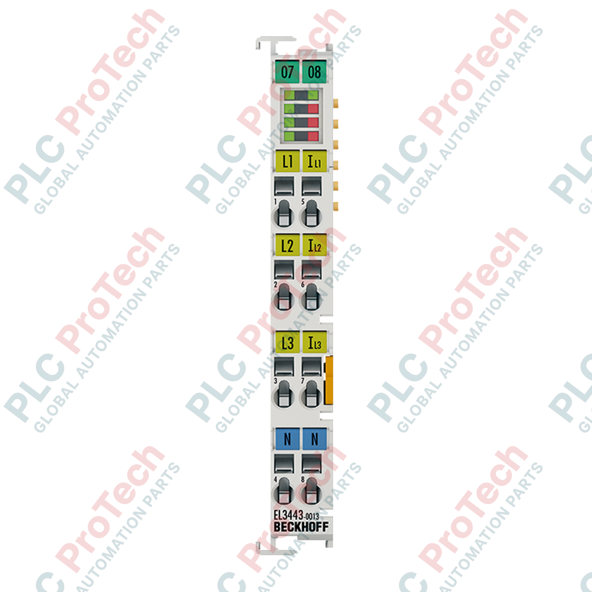
Designed for comprehensive and precise electrical network analysis, the Beckhoff EL3443-0013 serves as a high-performance 3-channel power measurement EtherCAT terminal. This module is engineered to evaluate non-sinusoidal AC and DC distribution systems directly, accommodating voltages up to 480 V AC. Utilizing 24-bit resolution analog inputs, it processes signals from low-voltage current transformers with a nominal output of 333 mV. This makes it an ideal instrument for integration into space-constrained control cabinets where detailed monitoring of effective, reactive, and apparent power, along with harmonic analysis up to the 40th harmonic, is required for preventative maintenance and active energy management.
Features
-
3-Phase Power Measurement: Features three independent current and three independent voltage measurement channels for complete grid diagnostics.
-
Low-Voltage Sensor Interface: Designed for safe and efficient interfacing with external 333 mV voltage-output current transformers.
-
Advanced Grid Analysis: Measures current, voltage, active/reactive/apparent power, energy values, cos phi, frequency, THD, and harmonics up to the 40th order.
-
Mains Synchronization: Provides net-synchronous updates with an interval of one mains period (20 ms at 50 Hz).
-
Compact Form Factor: Standard 12 mm EtherCAT terminal housing simplifies integration onto standard 35 mm DIN rails.
-
Zero Voltage Crossing Detection: Enables high-accuracy synchronization and phase order detection.
Applications
-
Industrial Energy Monitoring: Deployment in manufacturing facilities to trace, log, and optimize machinery power consumption.
-
Power Quality Auditing: Localized harmonic distortion and voltage anomaly analysis within busy automation networks.
-
Sub-Metering Infrastructures: Integration into distributed control systems to monitor individual assembly lines or plant zones.
Technical Specifications
| Parameter |
Value / Specification |
| Manufacturer |
Beckhoff Automation GmbH & Co. KG |
| Model Number |
EL3443-0013 |
| Number of Inputs |
3 x current, 3 x voltage |
| Measuring Technology |
3-phase power measurement |
| Max. Measuring Voltage |
480 V AC 3~ (ULX-N: max. 277 V AC/240 V DC) |
| Measuring Current Input |
333 mV (AC/DC) via external measurement transformers |
| Resolution |
24 bit |
| Measuring Error |
0.3% relative to full-scale value (U/I), 0.6% calculated value |
| Electrical Isolation |
2500 V |
| E-bus Current Consumption |
Typical 120 mA |
| Update Interval |
One mains period (20 ms at 50 Hz) |
| Operating Temperature |
0 to +55 degC |
| Storage Temperature |
-25 to +85 degC |
| Permissible Relative Humidity |
95%, non-condensing |
| Housing Material |
Polycarbonate |
| Connection Technology |
CAGE CLAMP spring actuation |
| Conductor Cross-Section |
Solid/Stranded: 0.08 to 2.5 mm2 (AWG 28...14) |
| Dimensions (W x H x D) |
12 mm x 100 mm x 68 mm |
| Country of Origin |
Germany |
| Shipping Weight (Calculated) |
0.15 kg |
Connections and Interfaces
| Terminal Connection |
Signal Assignment |
Description |
| L1 (1) |
Voltage Phase 1 |
Voltage input channel for phase 1 (L1) |
| L2 (2) |
Voltage Phase 2 |
Voltage input channel for phase 2 (L2) |
| L3 (3) |
Voltage Phase 3 |
Voltage input channel for phase 3 (L3) |
| N (5) |
Neutral Conductor |
Neutral connection for reference voltage |
| I1+ / I1- (9, 10) |
Current Channel 1 (333 mV) |
Differential low-voltage input for phase 1 current transformer |
| I2+ / I2- (11, 12) |
Current Channel 2 (333 mV) |
Differential low-voltage input for phase 2 current transformer |
| I3+ / I3- (13, 14) |
Current Channel 3 (333 mV) |
Differential low-voltage input for phase 3 current transformer |
Empirical Engineering Insights
Alternative Models & Compatibility
It is critical to distinguish the EL3443-0013 from the standard EL3443-0000. The standard model is configured for direct current measurements of up to 1 A or 5 A AC/DC. In contrast, the EL3443-0013 relies on low-power, voltage-output external sensors (333 mV). Interchanging these terminal types without matching the corresponding field current transformers will cause measurement saturation or catastrophic thermal failure of the inputs.
Application Pitfalls & Engineering Notes
When monitoring networks with significant variable frequency drive (VFD) loading, thermal load within the terminal housing can escalate due to harmonic current peaks. Ensure appropriate lateral space or active heat dissipation within the enclosure if the continuous phase-to-phase voltage remains consistently above 440 V AC. Never connect standard, current-output (x A / 1 A or x A / 5 A) current transformers directly to this module, as the low-voltage inputs cannot clamp the inductive surge of high-current secondary loops.
Commissioning & Wiring Tips
To ensure high-fidelity measurements, always implement shielded twisted pair (STP) wiring for the 333 mV transformer signal lines. The shielding should terminate directly to the functional ground (FE) of the DIN rail closest to the point of entry. In TwinCAT 3, configuration offsets must be applied via the CoE (CanOverEthernet) online parameterization menu to correlate the 333 mV signal range directly to the primary scaling values of the field sensors.
Installation Guidelines
CRITICAL WARNING: Prior to mounting, wiring, or maintenance on the terminal, de-energize the entire distribution network. Verify that the bus system and voltage inputs are fully isolated. Residual charges must be bled from the primary circuit to avoid fatal electric shock or damage to the internal analog converters.
1
Snap the terminal onto the grounded 35 mm DIN rail (conforming to EN 60715) using the integrated locking mechanism.
2
Connect the physical E-Bus logic path by sliding adjacent terminals together using the dual slot and key system.
3
Perform tool-actuated CAGE CLAMP spring wiring. Strip wire insulation to 8-9 mm before inserting conductors into terminal ports.
4
Verify signal routing: establish phase voltage inputs on connections 1, 2, and 3, and terminate current transformer inputs on connections 9 through 14.