Présentation du produit
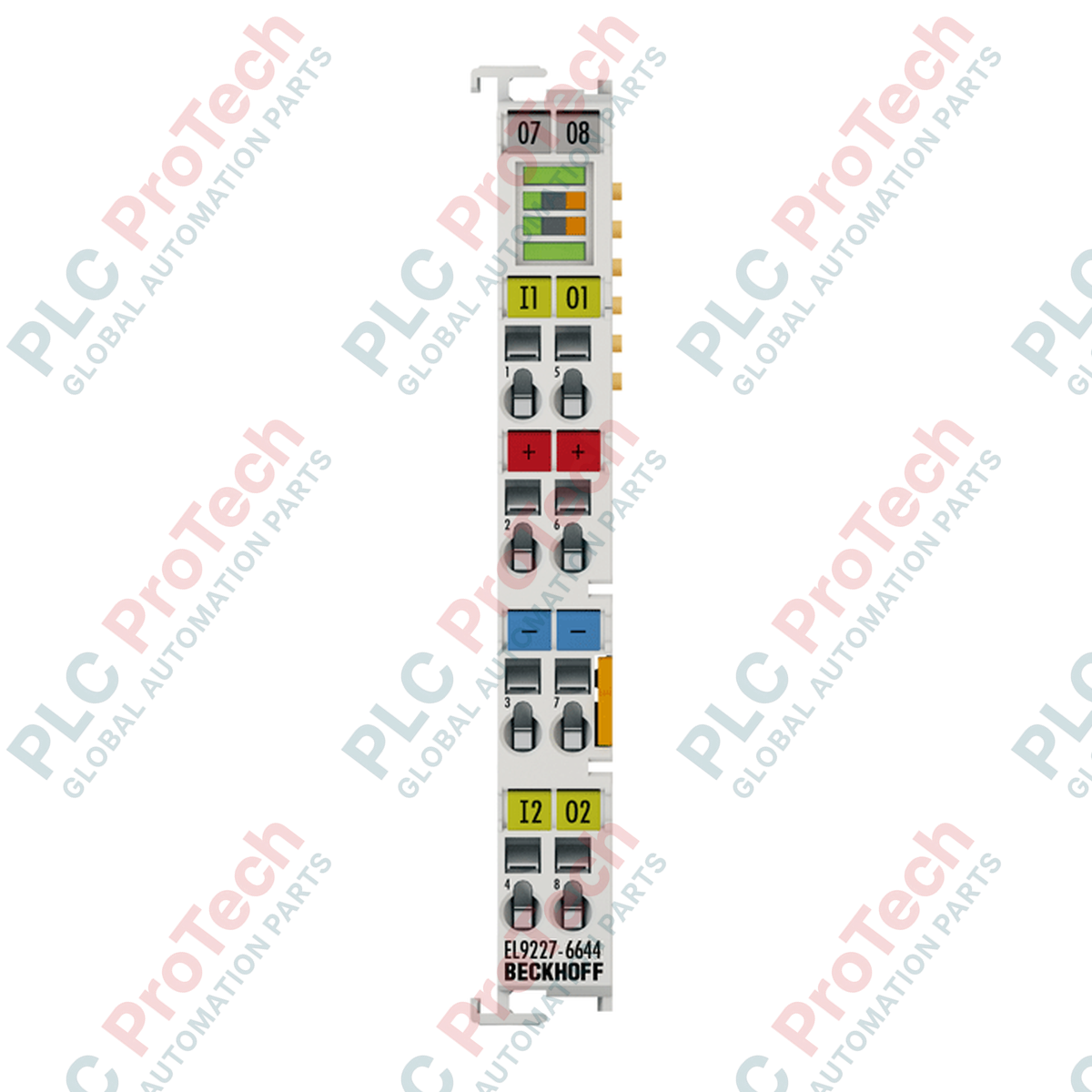
Le EL9227-6644 (EL9227-6644) est un terminal avancé de protection électronique contre les surintensités à 2 canaux conçu pour les réseaux de distribution d’alimentation 24 V DC. Avec une capacité de charge optimisée de 4 A par canal, ce module I/O EtherCAT haute performance offre des caractéristiques de déclenchement rapides et précises que les disjoncteurs mécaniques ne peuvent égaler.
En analysant en continu les courants de charge de sortie et les tensions du bus, le module isole les défauts électriques localisés avant qu’ils ne se propagent dans la boucle de contrôle. Il est largement utilisé dans les entrepôts automatisés à haute densité, les lignes d’assemblage automobile et les usines de processus continus, protégeant les processeurs PLC sensibles, les instruments de terrain et les capteurs tout en minimisant les arrêts imprévus des installations.
Protection de circuit et diagnostics intelligents
L’EL9227-6644 offre des fonctionnalités étendues permettant une paramétrisation détaillée des courbes de fusibles électroniques directement via le réseau EtherCAT. Il intègre un mécanisme d’alerte d’avance réglable pour les conditions de charge de sortie (de 50 % à 100 %) et un seuil d’alerte de sous-tension réglable (17 à 24 V DC) pour signaler une dégradation du système avant une coupure complète.
La sécurité matérielle est renforcée par des éléments intégrés de sécurité lente de 6 A par canal, une protection contre l’inversion de polarité et un circuit de coupure de surtension qui s’active lorsque la tension atteint ou dépasse 32 V DC. Une interface native à bouton LED sur le panneau avant offre une visualisation locale de l’état et la possibilité de réinitialiser manuellement les canaux, tandis que le canal 1 peut également acheminer le courant via le rail de contact d’alimentation physique.
Caractéristiques techniques
| Paramètre |
Spécifications |
| Modèle |
EL9227-6644 |
| Marque |
BECKHOFF |
| Origine |
Allemagne |
| Format d’interface |
Bornier EtherCAT (communication E-bus) |
| Tension nominale |
24 V DC |
| Nombre de canaux |
2 sorties protégées / 2 entrées numériques |
| Courant d’entrée maximal |
10 A |
| Courant de sortie nominal |
4 A par canal |
| Fusible de secours intégré |
6 A (T) | 6 A (T) |
| Coupure de surtension |
Supérieur ou égal à 32 V DC |
| Alerte de sous-tension |
Réglable ; 17 à 24 V DC |
| Alerte d’avance de charge |
Réglable ; 50 % à 100 % |
| Temps de maintien après refroidissement |
Supérieur ou égal à 10 s (dépendant de la température) |
| Arrêt arrière |
Réglable ; 3 niveaux |
| Consommation de courant E-bus |
Typ. 80 mA |
| Isolation électrique |
500 V (tension E-bus vers signal) |
| Dimensions (L x H x P) |
12 mm x 100 mm x 68 mm |
| Poids |
Environ 55 g |
| Température de fonctionnement |
0 à +55 °C |
| Température de stockage |
-25 à +85 °C |
| Indice de protection |
IP20 |
| Homologations et normes |
CE, cULus, cURus |
FAQ produit
Quel est le but du maintien thermique de 10 secondes après une coupure de sortie ?
Le temps de maintien minimum de 10 secondes garantit que les composants électroniques de commutation internes ont suffisamment refroidi après un événement majeur de surintensité ou de court-circuit. Ce blocage thermique empêche des réinitialisations manuelles ou automatiques rapides et répétées qui pourraient provoquer une défaillance thermique catastrophique du module ou des lignes terrain connectées.
Que permet la fonction de « coupure rétrograde en 3 étapes » ?
La coupure rétrograde est une fonction de diagnostic intelligente qui évalue la gravité et la localisation d’un défaut. Selon la paramétrisation des 3 étapes via TwinCAT, le module peut prioriser l’isolement du seul canal local, couper l’alimentation en amont ou exécuter un déclenchement différé pour permettre aux sous-circuits adjacents d’éliminer les courants d’appel transitoires.
L’EL9227-6644 peut-il être réinitialisé à distance après un déclenchement par court-circuit ?
Oui. Bien que les techniciens puissent appuyer manuellement sur le bouton LED intégré en façade pour effacer localement une condition de défaut, la borne mappe directement les mots de contrôle et d’état complets dans l’image de processus du maître EtherCAT, permettant des réinitialisations entièrement pilotées par logiciel depuis le programme PLC central.
Manuel d’ingénierie terrain et de sécurité
-
Protocole de terminaison des conducteurs : Ouvrez les serre-fils à ressort internes à l’aide d’un tournevis plat standard. Dénudez tous les fils sur une longueur de 8 à 9 mm. La borne accepte des fils rigides (e) ou multibrins (st) de calibre AWG 28 à 14, ainsi que des conducteurs isolés par embouts (f) de calibre AWG 26 à 16. Veillez à ce qu’aucune brin libre ne fasse de pont entre les points de connexion adjacents.
-
Équilibrage du courant du bus d’alimentation : Notez que la limite totale du courant d’entrée pour la borne est restreinte à un maximum de 10 A. Lors de la planification des agencements de panneaux, assurez-vous que la charge continue cumulée des deux canaux de sortie surveillés ainsi que toute alimentation en aval via les contacts d’alimentation partagés ne dépasse pas cette limite de 10 A en conditions de fonctionnement de pointe.
-
Mécanique de montage sur rail DIN : Clipsez le module verticalement sur un rail DIN standard de 35 mm conforme à la norme EN 60715. Assurez-vous que les doubles fentes d’emboîtement et les connexions à clé s’engagent parfaitement avec les bornes adjacentes. Cette configuration de verrouillage est obligatoire pour garantir la continuité stable du bus E-bus et la rigidité structurelle en cas de choc mécanique ou de vibration importants.