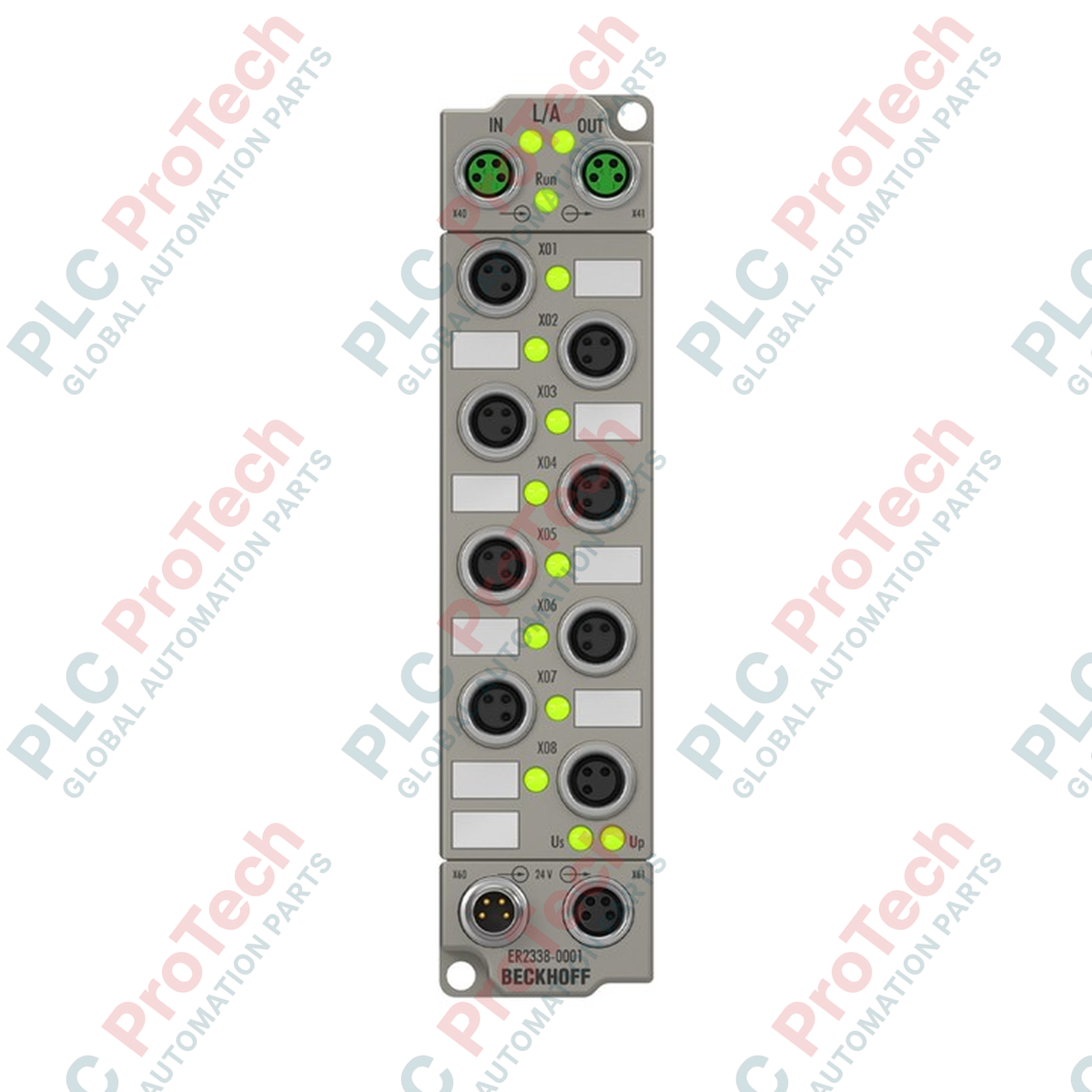
L'intégration directe au niveau physique des signaux décentralisés est réalisée via la Boîte EtherCAT Beckhoff ER2338-1001, qui dispose de huit canaux numériques bidirectionnels configurables librement, logés dans un boîtier robuste et résistant à l'humidité IP67. Ce module s'interface directement avec les capteurs et actionneurs au niveau machine, éliminant le besoin d'armoires de contrôle protectrices et réduisant le câblage sur le terrain.
Caractéristiques clés
-
E/S configurables librement : Chacun des 8 canaux peut être configuré indépendamment en entrée ou sortie numérique via le logiciel de contrôle TwinCAT.
-
Commutation haute vitesse : Dispose de temps de commutation rapides avec un temps d'activation typique de 50 microsecondes et un temps de désactivation de 100 microsecondes.
-
Connectivité M8 robuste : Équipé de connecteurs M8 à vis blindés et sécurisés pour la communication EtherCAT et les canaux d'E/S physiques.
-
Protection complète : Protection intégrée contre les courts-circuits pour l'alimentation des capteurs et les sorties, avec un indice de protection IP65/66/67.
-
Isolation électrique : Fournit une isolation électrique de 500 V pour protéger l'électronique de contrôle en amont des interférences électriques côté terrain.
Applications industrielles
-
Lignes d'assemblage automobile : Montage direct sur bras robotiques et systèmes de convoyeurs où l'espace est limité et l'exposition aux fluides fréquente.
-
Machines d'emballage : Tri à grande vitesse, comptage et actionnement de vannes pneumatiques sans armoires terminales localisées.
-
Systèmes de manutention : Réseaux de capteurs distribués le long de longues lignes de convoyeurs utilisant une topologie EtherCAT en chaîne.
-
Transformation alimentaire et boissons : Déploiements en zones humides nécessitant des modules bus de terrain IP67 compatibles avec le lavage.
Caractéristiques techniques
| Paramètre |
Valeur / spécification |
| Fabricant |
Beckhoff Automation |
| Modèle / numéro d'article |
ER2338-1001 |
| Protocole |
EtherCAT |
| Interface bus |
2 x prise M8, blindée, à vis |
| Nombre de canaux |
8 entrées ou sorties numériques (configurables librement) |
| Connexions entrée/sortie |
M8 x 1, 3 broches, codage A |
| Temps de filtrage d'entrée |
3,0 ms |
| Tension du signal "0" |
-3 à +5 V |
| Tension du signal "1" |
11 à 30 V (courant d'entrée 6 mA, EN 61131-2, type 3) |
| Alimentation du capteur |
Dérivé de la tension d'alimentation de charge, max. 0,5 A au total, protégé contre les courts-circuits |
| Types de charge pris en charge |
Charge ohmique, inductive, lampe |
| Tension de charge nominale |
24 V CC (-15 % / +20 %) |
| Courant de sortie max. |
0,5 A par canal |
| Consommation de courant depuis l'US |
120 mA |
| Connexion d'alimentation |
Alimentation : 1 x M8 mâle, 4 broches ; Sortie : 1 x M8 femelle, 4 broches |
| Isolation électrique |
500 V |
| Température de fonctionnement |
-25 à +60 °C |
| Température de stockage |
-40 à +85 °C |
| Indice de protection |
IP65/66/67 (conforme à EN 60529) |
| Homologations |
CE, UL |
| Pays d'origine |
Allemagne |
| Poids d'expédition (calculé) |
2,0 kg |
| Dimensions du boîtier (calculées) |
150 x 50 x 40 mm |
Connexions et interfaces
| Type de connecteur |
Numéro de broche |
Affectation des fonctions |
| Prises M8 E/S (3 broches) |
Broche 1 |
+24 V CC alimentation capteur (US) |
| Broche 3 |
Masse (US) |
| Broche 4 |
Signal Entrée/Sortie (configurable) |
| Alimentation M8 (4 broches) |
Broche 1 |
+24 V CC alimentation contrôle (US) |
| Broche 2 |
+24 V CC alimentation périphérique (UP) |
| Broche 3 |
Masse (US) |
| Broche 4 |
Masse (UP) |
Aperçus empiriques d'ingénierie
Modèles alternatifs et compatibilité
Le ER2338-1001 possède un boîtier en plastique conçu pour des environnements industriels standards. Pour des applications nécessitant une résistance mécanique extrême ou une résistance aux solvants chimiques agressifs, le EP2338-1001 (boîtier en zinc moulé sous pression) constitue l'équivalent fonctionnel direct. Les deux modules partagent des fichiers de description XML (ESI) identiques dans TwinCAT, permettant un remplacement direct sans modification logicielle.
Pièges d'application et notes d'ingénierie
Lors de l'utilisation des canaux en sortie, assurez-vous que la consommation totale de courant de tous les actionneurs connectés ne dépasse pas les limites de dissipation thermique du module. Bien que chaque canal puisse commuter jusqu'à 0,5 A, une utilisation simultanée à fort cycle de service de toutes les sorties à charge maximale en températures ambiantes élevées (au-dessus de 50 °C) peut déclencher une coupure thermique interne. Calculez toujours la charge cumulée sur les chemins d'alimentation US et UP.
Conseils de mise en service et de câblage
Pour garantir l'étanchéité IP67, les ports M8 inutilisés doivent être scellés avec des capuchons de protection industriels. Lors du câblage de la communication EtherCAT, utilisez uniquement des câbles M8 à paires torsadées doublement blindées. Les boucles de masse peuvent être évitées en assurant que les pattes métalliques de fixation du module sont reliées directement à une masse machine propre et à faible impédance, plutôt que de compter uniquement sur le blindage du câble.
Consignes d'installation
AVERTISSEMENT CRITIQUE : Coupez l'alimentation de toutes les sources d'énergie du système (alimentation US pour contrôle/capteur et alimentation UP pour actionneur) avant de commencer l'installation, le câblage ou le remplacement du module. Le branchement à chaud des connecteurs M8 d'E/S ou d'alimentation peut provoquer des arcs électriques transitoires, entraînant des dommages permanents au circuit intégré transceiver EtherCAT interne.
1
Montez le module sur une surface plane et résistante aux vibrations à l'aide de deux vis M3. Assurez-vous que la surface de montage est propre et dépourvue de peinture pour établir une bonne connexion à la terre via les œillets de fixation.
2
Connectez le câble réseau EtherCAT entrant à la prise M8 gauche (IN) et le câble en aval à la prise M8 droite (OUT). Serrez les colliers de verrouillage M8 à 0,4 Nm.
3
Câblez le connecteur d'alimentation M8 en veillant à bien séparer les circuits d'alimentation US (système/capteur) et UP (actionneur/charge) afin de maintenir l'isolation électrique.
4
Analysez le réseau EtherCAT dans TwinCAT System Manager pour détecter automatiquement le module, puis configurez le mode de fonctionnement de chaque canal (Entrée ou Sortie) dans les paramètres des données de processus.