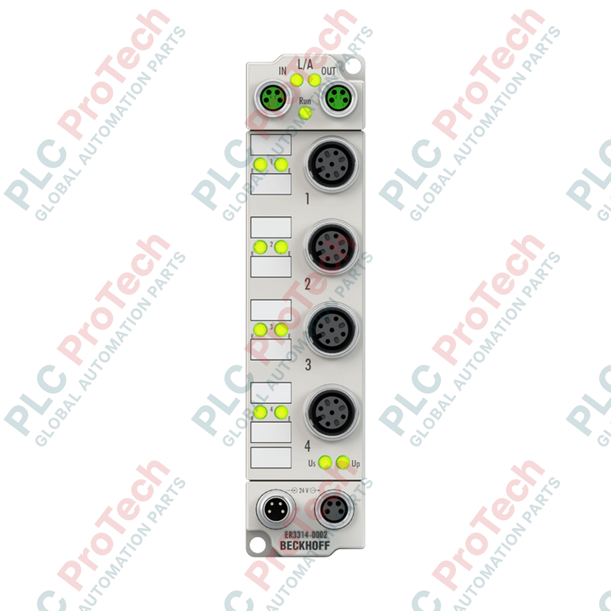
Description
Direct processing of up to four thermocouple sensors in harsh industrial environments is enabled by the Beckhoff ER3314-0002, an IP67-rated EtherCAT Box designed for decentralized temperature acquisition. Operating directly in the field, this space-saving module converts thermoelectric voltages from various sensor types (J, K, L, B, E, N, R, S, T, and U) into high-resolution temperature values, routing them straight to the controller without requiring a local electrical cabinet. System integrators benefit from native TwinCAT compatibility, configurable input filters, and robust electrical isolation, ensuring precise thermal profiling even under severe electromagnetic and environmental stress.
Features
-
Multi-Sensor Support: Built-in compatibility with ten distinct thermocouple classifications and direct millivolt (mV) voltage measurements.
-
Decentralized IP67 Housing: Fully encapsulated zinc die-cast housing provides extreme protection against moisture, dust, and mechanical impact.
-
M12 Connection Technology: Secure 2-wire thermocouple connections via standardized M12 screw sockets to resist high-vibration applications.
-
Advanced Diagnostics: Built-in open-circuit recognition and sensor failure detection reported directly over the EtherCAT process data image.
-
Configurable Filtering: Five software-configurable input filter variations to eliminate high-frequency electrical noise and line interference.
Applications
- Decentralized temperature measurement on plastic injection molding and extrusion machinery.
- Multi-zone thermal tracking in industrial glass, ceramic, and metallurgical kilns.
- Field-level environmental testing and climatic chamber monitoring.
- Exhaust gas and cooling system measurement in heavy-duty engine testing beds.
Technical Specifications
| Parameter |
Specification |
| Manufacturer |
Beckhoff Automation GmbH & Co. KG |
| Model / Part Number |
ER3314-0002 |
| Number of Inputs |
4 channels |
| Sensor Types Supported |
Types J, K, L, B, E, N, R, S, T, U (default: Type K), mV measurement |
| Measuring Range |
Sensor-dependent (Type K: -100 to +1370 degC) |
| Resolution |
0.1 degC per digit |
| Measurement Error |
Less than +/-0.3% of full-scale value (Type K) |
| Conversion Time |
2.5 s down to 20 ms (configurable; default: ~250 ms) |
| Bus Interface |
2 x M8 socket, shielded, screw-type (EtherCAT) |
| Nominal Supply Voltage |
24 V DC (-15% / +20%) |
| Current Consumption from US |
120 mA |
| Electrical Isolation |
500 V RMS |
| Protection Rating |
IP65 / IP66 / IP67 (conforms to EN 60529) |
| Operating / Storage Temp |
-25 to +60 degC / -40 to +85 degC |
| Approvals |
CE, UL |
| Country of Origin |
Germany |
| Net Weight |
0.265 kg |
| Shipping Weight (Calculated) |
2.0 kg (with protective commercial packaging) |
Connections and Interfaces
| Connector Pin / Terminal |
Function / Circuit Assignment |
| M12 Sockets (Channels 1 to 4) |
Thermocouple Connection (2-wire input: TC+ and TC-) |
| M8 Male Socket (Feed) |
Power Supply IN (24 V DC Control Voltage US / Sensor Supply UP) |
| M8 Female Socket (Downstream) |
Power Supply OUT (Looping power to downstream EtherCAT boxes) |
| M8 Sockets (EtherCAT Link) |
EtherCAT IN / EtherCAT OUT (100 Mbps communication lines) |
Alternative Models & Compatibility
The ER3314-0002 features a zinc die-cast housing designed to offer superior mechanical protection compared to the plastic-housed EP3314-0002 variant, though they remain functionally and programmatically identical. For setups requiring higher channel density in a control cabinet rather than field mounting, standard EtherCAT Terminals such as the EL3314 can be utilized within an E-bus segment. Both systems map to the exact same process image, allowing seamless code translation and direct parameter reuse in TwinCAT PLC configurations.
Application Pitfalls & Engineering Notes
Due to the high thermal mass of the zinc die-cast chassis, sudden environmental temperature changes near the module can cause temporary localized gradients across the cold junction. To prevent measurement errors during rapid ambient fluctuations, avoid mounting the box directly adjacent to heat sources or in areas experiencing severe draft currents. Unshielded thermocouple wires are highly susceptible to electromagnetic coupling; always maintain proper isolation from high-voltage variable frequency drive (VFD) cabling and use shielded thermocouple cables where possible.
Commissioning & Wiring Tips
When configuring the module within TwinCAT System Manager, navigate to the CoE (CAN over EtherCAT) online directory (specifically index 0x80n0) to select the correct thermocouple curve matching your physical sensor. By default, the module is configured for Type K thermocouples. Ensure the shield wire of the thermocouple cable is correctly terminated at the M12 connector casing to establish a continuous path to local ground, minimizing common-mode interference on the low-signal mV inputs.
Installation Guidelines
CRITICAL WARNING
Ensure all power sources (US and UP) are completely de-energized before mounting, grounding, or connecting signal lines to the device. Failing to disable live power lines can cause permanent transceiver failure or damage the sensitive analog conversion circuitry on the thermocouple input channels.
1
Securely mount the EtherCAT Box onto a flat, vibration-resistant surface using two M3 bolts through the pre-drilled integrated mounting holes.
2
Connect the local functional earth grounding wire to the ground lug on the module casing to ensure proper shielding performance.
3
Attach shielded M8 EtherCAT communication cables and M12 thermocouple sensors, tightening all connectors to their designated torque spec to preserve the IP67 integrity.