Description
Processing analog input signals within the Beckhoff I/O system, the BECKHOFF KL3042 Bus Terminal features two channels designed to acquire standard industrial currents ranging from 0 to 20 mA. This 12-bit resolution terminal operates on a single-ended technology scheme, providing highly reliable communication to the upper-level K-bus. By integrating an onboard sensor supply, this device minimizes the need for external distribution terminals, streamlining cabinet wiring in space-constrained industrial installations.
Features
- Two single-ended analog input channels for standard current-loop signals
- 12-bit digitization resolution for precise monitoring of process variables
- Integrated sensor supply connection points routing 24 V DC directly to field transmitters
- High-speed conversion timing optimizing PLC cycle responsiveness
- Compact 12 mm housing width maximizing DIN-rail spatial density
- Galvanic isolation rated at 500 V protecting the internal K-bus architecture
Applications
- Continuous process monitoring (flowmeters, pressure transducers, level indicators)
- HVAC environmental monitoring and pneumatic damper positioning systems
- Water and wastewater municipal pump control panels
- Factory automation machinery utilizing standard 0 to 20 mA loop transmitters
Technical Specifications
| Parameter |
Specification Value |
| Manufacturer |
Beckhoff Automation |
| Model Series |
KL Bus Terminal Series |
| Number of Inputs |
2 channels |
| Signal Current Range |
0 to 20 mA |
| Resolution |
12-bit |
| Technology Type |
Single-ended |
| Internal Resistance |
80 ohms + diode voltage 0.7 V |
| Conversion Time |
approx. 2 ms |
| Measurement Uncertainty |
< +/-0.3 percent (relative to full scale value) |
| Surge Voltage Resistance |
max. 35 V DC |
| Electrical Isolation |
500 V (K-bus / signal voltage) |
| Current Consumption (K-bus) |
typ. 65 mA |
| Process Image Bit Width |
Input: 2 x 16-bit data (2 x 8-bit control/status optional) |
| Operating Temperature |
-25 to +60 degC |
| Storage Temperature |
-40 to +85 degC |
| Relative Humidity |
95 percent, non-condensing |
| Protection Rating |
IP20 (variable installation position) |
| Approvals & Markings |
CE, UL, ATEX, IECEx, DNV GL |
| Ex Marking |
ATEX: II 3 G Ex ec IIC T4 Gc / IECEx: Ex ec IIC T4 Gc |
| Country of Origin |
Germany |
| Shipping Weight (Calculated) |
0.07 kg (exclusive of protective packaging) |
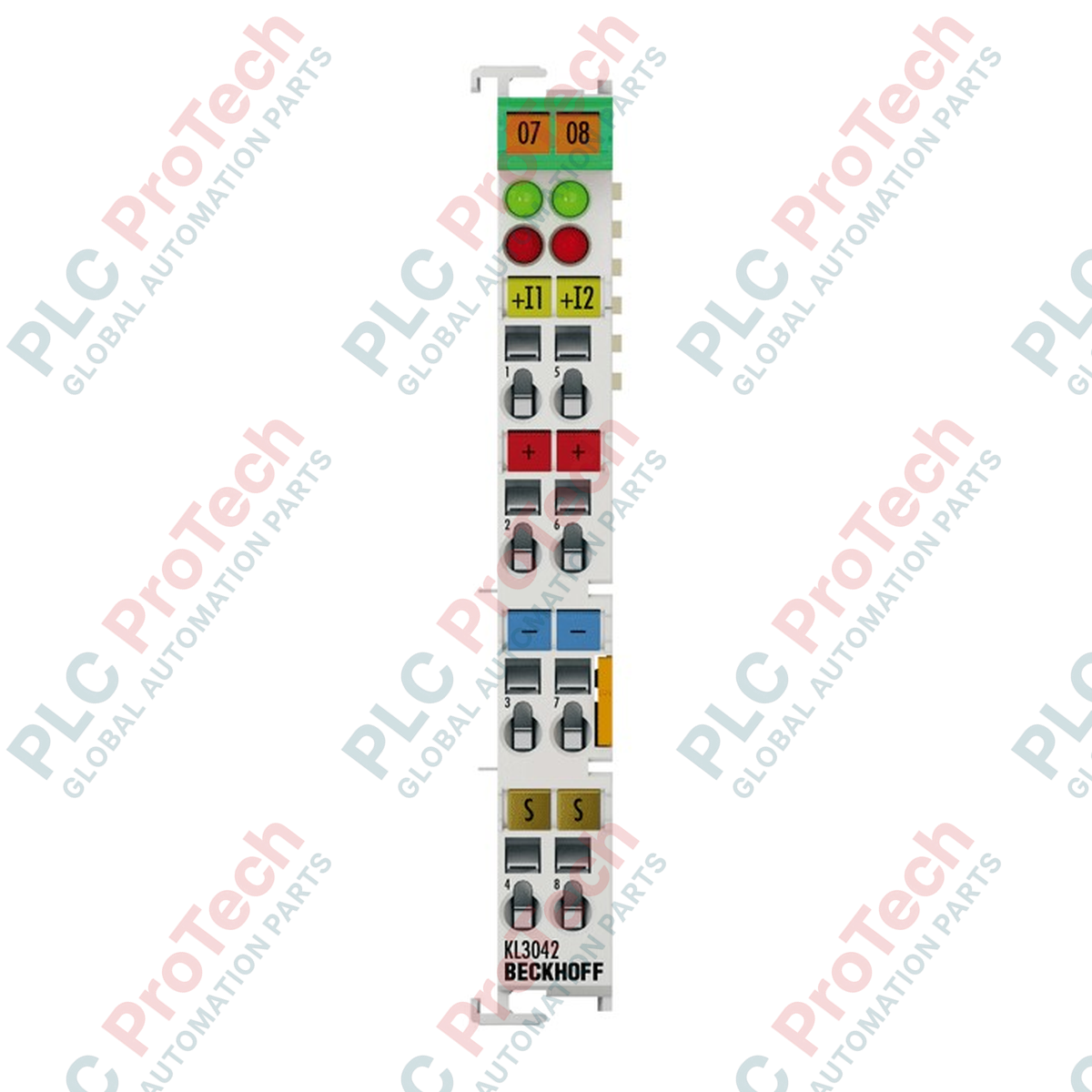
Connections and Interfaces
| Terminal Connection Point |
Functional Assignment |
| 1 |
Analog Input 1 (+) |
| 2 |
Sensor Supply 1 (+24 V DC) |
| 3 |
0 V Sensor Supply (connected internally with point 7) |
| 4 |
Shield / Functional Earth (PE) |
| 5 |
Analog Input 2 (+) |
| 6 |
Sensor Supply 2 (+24 V DC) |
| 7 |
0 V Sensor Supply (connected internally with point 3) |
| 8 |
Shield / Functional Earth (PE) |
Empirical Engineering Insights
Alternative Models & Compatibility
For installations requiring fast-disconnect options or pre-wired cable harnesses, transition to the KS3042 model, which features pluggable connection blocks with identical technical ratings. Ensure the K-bus coupler (e.g., BK9000 or BK1100) firmware is up to date to properly map the 2 x 16-bit process image in your TwinCAT System Manager software configuration.
Application Pitfalls & Engineering Notes
Because this is a single-ended input card, all channels share an internal common reference point. Connecting loop transmitters that have distinct, non-isolated grounds can generate ground-loop currents, resulting in measurement deviations or card errors. If utilizing active, externally powered 4-wire transmitters, ensure the loop signal remains isolated or shares a common 0 V DC potential with the cabinet supply bus.
Commissioning & Wiring Tips
Always route current loop cabling using shielded, twisted-pair lines. Terminate the shield directly to connections 4 and 8 (PE) at the terminal, or land them on an auxiliary shield clamp bus bar positioned directly at the entry of the control panel to minimize electromagnetic interference from neighboring variable frequency drives.
Installation Guidelines
CRITICAL WARNING: De-energize all primary and auxiliary power contacts before inserting or removing any Bus Terminals from the node segment. Failure to do so can cause electric arcing, leading to physical damage to the internal K-bus contacts and system communications failure.
1
Mount the bus coupler on a standard 35 mm DIN rail (EN 60715) and lock it into place using the integrated rail clamp.
2
Slide the module along the guide slot of the adjacent terminal until the tongue-and-groove joint is fully locked.
3
Press the module firmly against the DIN rail until the side latching mechanism clicks, indicating secure grounding contact.
4
Using a standard flat-head screwdriver, insert wire leads into the tension clamp connection points and release the spring mechanism to complete the connection.