Description
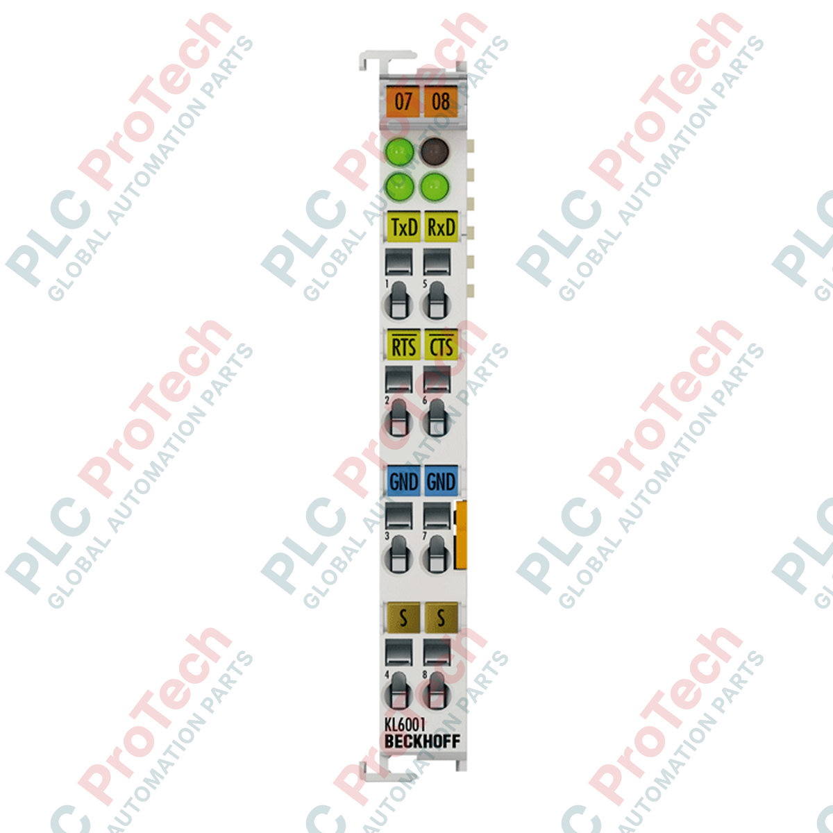
Operating as a dedicated serial interface within the Beckhoff I/O framework, this Beckhoff KS6001 Bus Terminal enables the direct integration of RS232-compatible devices into the control network. It establishes a robust bi-directional connection, facilitating full-duplex data transmission through RxD and TxD channels with high electromagnetic interference immunity. The module features pluggable wiring levels, allowing rapid field installation and maintenance without disrupting the existing terminal wiring setup. It communicates directly with the controller through the K-bus, offering an isolated, compact footprint for industrial serial communication.
Features
-
Pluggable Connection Design: Features a removable wiring tier for fast servicing and drop-in channel replacements.
-
High Noise Immunity: Electrically isolated signals protect the internal K-bus architecture from electrical surges up to 500 V.
-
Flexible Process Image: Configurable bit-width structures in the process image (up to 5 x 8-bit user data) to accommodate variable protocol lengths.
-
Integrated Data Buffers: Equipped with a 128-byte receive buffer and a 16-byte transmit buffer to handle continuous serial data streams.
-
Rugged DIN-Rail Mounting: Direct installation onto standard 35 mm DIN rails with integrated lock mechanisms.
Applications
- Integration of legacy barcode scanners, printers, and operator panels into EtherCAT or Lightbus networks.
- Point-to-point communication with analytical laboratory instruments and industrial weighing scales.
- Interfacing with proprietary serial sensor arrays and legacy telecommunication modems in power distribution panels.
Technical Specifications
| Parameter |
Value / Specification |
| Manufacturer |
Beckhoff Automation |
| Model / Part Number |
KS6001 |
| Technology |
RS232 serial interface |
| Data Transfer Channels |
2 (1 transmit / 1 receive), TxD and RxD, full duplex |
| Data Transfer Rates |
1200 to 19,200 baud (Default: 9600 baud, 8 data bits, no parity, 1 stop bit) |
| Bit Distortion |
Less than 3 percent |
| Maximum Cable Length |
15 meters |
| Signal Voltage Range |
Logical 0: -18 V to -3 V | Logical 1: 3 V to 18 V |
| Current Consumption (K-bus) |
Typical 55 mA |
| Electrical Isolation |
500 V (K-bus to signal voltage) |
| Data Buffers |
128 bytes receive buffer, 16 bytes transmit buffer |
| Process Image Bit Width |
Input/Output: 3 x 8-bit user data, 1 x 8-bit control/status (up to 5 x 8-bit user data) |
| Wiring Connection |
Solid conductor (e), flexible (f), ferrule (a); spring-actuated clamp |
| Connection Cross-Section |
0.08 to 1.5 mm2 (AWG 28 to 16) |
| Stripping Length |
9 to 10 mm |
| Dimensions (W x H x D) |
12 mm x 100 mm x 68 mm |
| Operating / Storage Temp. |
0 to +55 degC / -25 to +85 degC |
| Relative Humidity |
95 percent, non-condensing |
| Protection Rating |
IP20 / variable installation position |
| Approvals & Markings |
CE, UL, ATEX (II 3 G Ex nA IIC T4 Gc) |
| Country of Origin |
Germany |
| Shipping Weight (Calculated) |
1.5 kg |
Empirical Engineering Insights
Alternative Models & Compatibility
The KS6001 module is functionally identical to the standard KL6001 terminal. The critical differentiator lies in the pluggable connection block on the KS series, which permits hot-swapping or physical component replacement without requiring the field wires to be individually disconnected. Both models use the identical TwinCAT process image, making them completely interchangeable from a software and program mapping perspective.
Application Pitfalls & Engineering Notes
Because this module utilizes standard RS232 single-ended signals, maximum physical cable runs must be restricted to 15 meters to prevent signal attenuation and susceptibility to external electromagnetic fields. If the module is deployed in close proximity to high-frequency AC variable frequency drives (VFDs) or heavy inductive loads, you must run double-shielded, low-capacitance cabling directly to the terminal, terminating the shield at a dedicated functional ground busbar external to the module.
Commissioning & Wiring Tips
When configuring the serial parameters in TwinCAT System Manager, verify that the baud rate, parity, data bits, and stop bits precisely match your connected end device. A mismatch will fail to establish communication and may lock up the internal buffers. When designing the logic, monitor the 1-byte control/status process image to implement proper software handshaking, since this terminal does not utilize hardware CTS/RTS handshaking lines.
Installation Guidelines
CRITICAL WARNING
Prior to installing or removing the terminal block, completely isolate the system power supply. Ensure all auxiliary voltages feeding the terminal and any associated field instruments are fully de-energized. Failure to isolate power can result in terminal damage, system communication faults, or spark ignition risks in hazardous ATEX zones.
1
Mount the module onto a standard 35 mm DIN rail (conforming to EN 60715). Ensure the rear lock slides securely over the rail profiles.
2
Align the terminal side-by-side with adjacent K-bus terminals to engage the integrated double slot and key connection points on the housing sides.
3
Strip wire insulation back by exactly 9 to 10 mm. Use a small screwdriver flat blade to open the spring clamp mechanics on the pluggable wiring block, insert the conductor, and release to secure.
4
Plug the wired connector block back into the module housing. Turn on system power and initiate configuration within your PLC system environment.