Présentation du produit
Le KS4021 (KS4021) Bus Terminal traite des signaux de commande analogiques dans la plage de 4 à 20 mA avec une résolution de 12 bits. Conçu pour des environnements industriels difficiles tels que la chimie, les stations d’épuration et les centrales électriques, ce module de sortie analogique simple extrémité transmet des signaux avec isolation galvanique jusqu’au niveau de l’actionneur. Son design compact et haute efficacité répond directement aux risques d’arrêt industriel en utilisant des niveaux de câblage enfichables, permettant un remplacement rapide sur site sans déconnecter les fils individuels du bornier. Fonctionnant sur le système K-bus Beckhoff éprouvé, le module assure une communication de données fiable et en temps réel vers le contrôleur PLC ou IPC central.
Configuration technique
Le KS4021 présente une topologie de circuit simple extrémité, optimisée pour les armoires de commande à espace restreint où un routage individuel des canaux est requis. Il reçoit l’alimentation directement des contacts d’alimentation 24 VDC, bien qu’il supporte une alimentation alternative 15 VDC via un bornier d’alimentation KL9515 pour s’adapter aux architectures système spécialisées.
L’image de processus utilise 1 x données 16 bits, avec un octet de contrôle et d’état optionnel 1 x 8 bits pour un diagnostic avancé. Elle ne nécessite aucune configuration matérielle ni réglage d’adresse, permettant une intégration purement plug-and-play dans l’environnement d’ingénierie TwinCAT. Le boîtier du bornier dispose d’un système de connexion à double fente et clé pour un montage robuste côte à côte sur rail DIN.
Spécifications techniques
| Paramètre |
Spécifications |
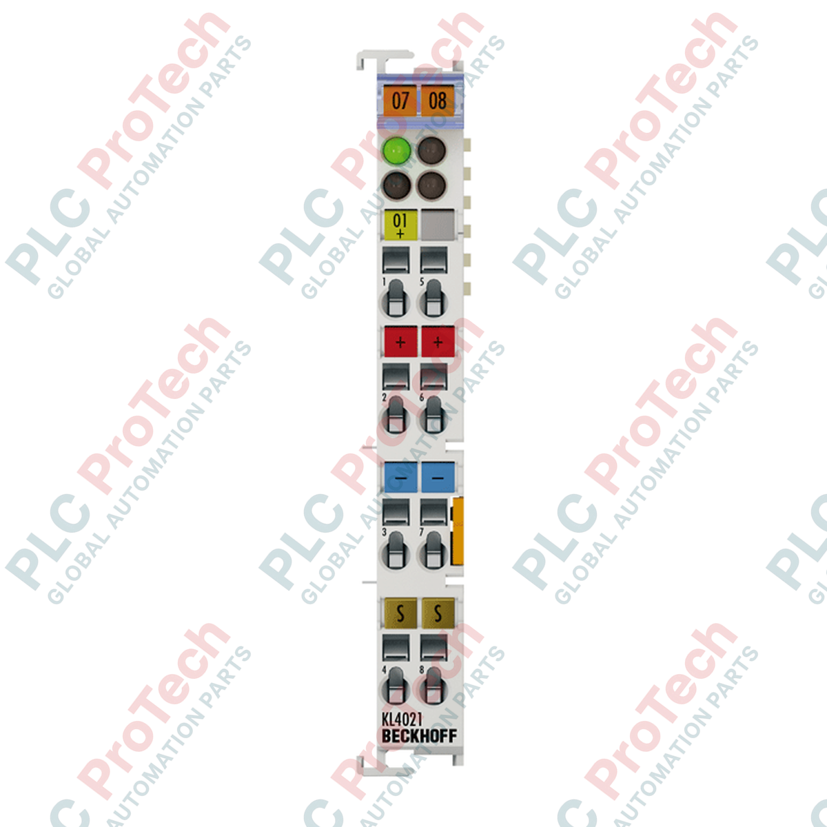
| Modèle |
KS4021 |
| Marque |
BECKHOFF |
| Origine |
Allemagne |
| Technologie |
Simple extrémité |
| Nombre de sorties |
1 |
| Alimentation |
24 VDC via contacts d’alimentation (alternatif 15 VDC avec KL9515) |
| Courant de signal |
4 à 20 mA |
| Résistance de charge |
Moins de 500 Ohm |
| Erreur de sortie |
Moins de +/-0,1 % (par rapport à la valeur finale) |
| Résolution |
12 bits |
| Temps de conversion |
Environ 1,5 ms |
| Isolation électrique |
500 V (K-bus vers tension de signal) |
| Consommation de courant (contacts d’alimentation) |
Typ. 30 mA + charge |
| Consommation de courant (K-bus) |
Typ. 60 mA |
| Dimensions (L x W x H) |
6,8 cm x 1,2 cm x 10,0 cm |
| Poids |
0,08 kg |
| Température de fonctionnement |
0 à +55 °C |
| Température de stockage |
-25 à +85 °C |
| Humidité relative |
95 %, sans condensation |
| Indice de protection |
IP20 |
| Homologations / Marquages |
CE, UL, ATEX, DNVGL |
| Marquage Ex |
II 3 G Ex nA IIC T4 Gc |
FAQ produit
Quelle est la différence pratique entre le KS4021 et le KL4021 ?
La principale différence réside dans la conception du boîtier. Le KS4021 dispose d'un niveau de câblage amovible, permettant de remplacer toute l'électronique du bornier tout en laissant le câblage sur site intact. Le KL4021 utilise des bornes de câblage fixes où les câbles doivent être déconnectés individuellement lors de la maintenance.
Comment le module gère-t-il les erreurs de sortie si la résistance de charge dépasse 500 Ohms ?
Si la résistance totale de la boucle dépasse 500 Ohms, le convertisseur numérique-analogique interne saturera. Cela empêche le module de fournir le courant complet de 20 mA, entraînant un signal de sortie inexact et déclenchant un bit d'état d'erreur dans l'image de processus du PLC.
Ce bornier nécessite-t-il une configuration manuelle dans TwinCAT ?
Aucune configuration manuelle d'adresse ou de paramètre n'est requise sur le matériel lui-même. Le K-bus détecte automatiquement le type et la position du module au démarrage du système, mappant directement les données de sortie 16 bits dans la configuration du contrôleur.
Instructions d'installation et de câblage sur site
-
Fonctionnement du bornier amovible : Pour libérer ou insérer des fils individuels, utilisez un tournevis à fente standard pour actionner le mécanisme de pince de tension intégré. Dénudez tous les fils de signal à exactement 9 à 10 mm. Assurez-vous que la section de connexion correspond à la spécification (AWG 28 à 16 pour fils pleins ou multibrins).
-
Blindage et atténuation du bruit : Pour les environnements industriels à forte interférence électromagnétique (EMI), utilisez toujours des câbles torsadés blindés pour la boucle 4 à 20 mA. Mettez la masse du blindage du câble à la terre à une seule extrémité — idéalement au point d'entrée de l'armoire de commande — pour éviter les boucles de masse.
-
Exigences de sécurité ATEX Zone 2 : Lors de l'installation du module dans des zones dangereuses marquées II 3 G Ex nA IIC T4 Gc, le bornier doit être monté à l'intérieur d'un boîtier classé IP54 conforme à la norme EN 60079-15. Ne déconnectez pas et n'insérez pas les leviers de câblage amovibles lorsque le système est sous tension.