Présentation du produit
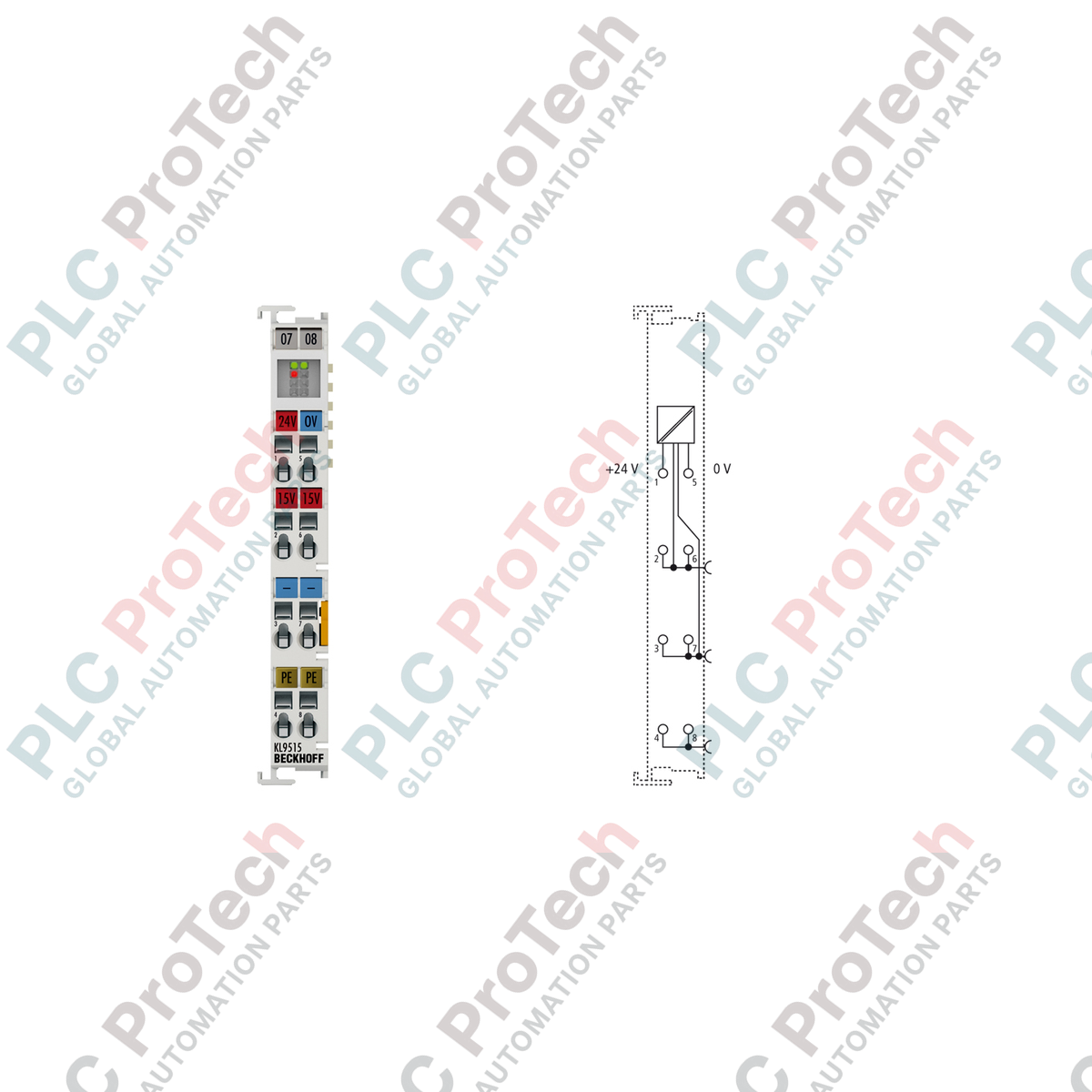
Le KS9515 (KS9515) Bornier d’alimentation convertit une tension d’entrée standard de 24 VCC en une tension de sortie régulée et très stable de 15 VCC. Conçu pour les réseaux d’automatisation industrielle, les usines de fabrication et les environnements de process, ce module abaisse la puissance en toute sécurité pour alimenter des dispositifs de terrain spécifiques et des borniers de bus analogiques spécialisés, tels que le KS4021. En fournissant une alimentation propre et à faible ondulation directement sur le rail DIN, le module isole les instruments sensibles en aval des bruits importants du système, réduisant ainsi les pannes matérielles imprévues et minimisant les temps d’arrêt de l’installation. Il utilise un niveau de câblage enfichable caractéristique de la série Beckhoff KS, permettant une maintenance aisée et le remplacement des composants sans nécessiter de reconstruction fil par fil du bornier.
Configuration technique
Le KS9515 dispose d’un bloc convertisseur DC-DC interne conçu pour gérer des variations d’entrée allant de -15 % à +20 %. Il fournit une sortie précise de 15 VCC (+/-1 %) jusqu’à une capacité de courant maximale de 0,5 A. Une LED de surcharge intégrée offre un diagnostic visuel en temps réel directement sur le panneau avant, alertant immédiatement les techniciens de terrain en cas de surcharge.
L’architecture matérielle intègre une protection complète contre les courts-circuits et un profil d’ondulation résiduelle limité à moins de 5 mV, ce qui en fait un choix idéal pour les boucles de capteurs haute précision. Le boîtier du bornier présente une largeur standard de 12 mm avec une double fente et un système de clé, permettant un verrouillage et une intégration côte à côte avec les modules de communication K-bus standard.
Caractéristiques techniques
| Paramètre |
Spécifications |
| Modèle |
KS9515 |
| Marque |
BECKHOFF |
| Origine |
Allemagne |
| Tension d'entrée |
24 VCC (-15 % / +20 %) |
| Tension de sortie |
15 VCC +/-1 % |
| Courant de sortie |
0,5 A |
| Protégé contre les courts-circuits |
Oui |
| Ondulation résiduelle |
Moins de 5 mV |
| Indicateurs de diagnostic |
LED de surcharge |
| Conception du boîtier |
Polycarbonate avec niveau de câblage enfichable |
| Dimensions (L x H x P) |
12 mm x 100 mm x 68 mm |
| Poids |
Environ 65 g |
| Température de fonctionnement |
0 à +55 °C |
| Température de stockage |
-25 à +85 °C |
| Humidité admissible |
95 %, sans condensation |
| Indice de protection |
IP20 |
| Homologations et marquages |
CE, UL, ATEX |
| Marquage de zone dangereuse |
II 3 G Ex nA IIC T4 Gc |
FAQ produit
Comment la LED de surintensité aide-t-elle au dépannage sur le terrain ?
La LED de surintensité intégrée s’allume lorsque la charge connectée à la sortie 15 VCC dépasse la limite de conception de 0,5 A ou en cas de court-circuit direct. Le module limite le courant de sortie en toute sécurité jusqu’à ce que la condition de défaut soit levée, évitant ainsi tout dommage thermique au bornier ou aux modules K-bus adjacents.
Le KS9515 peut-il alimenter plusieurs modules analogiques simultanément ?
Oui, à condition que la consommation totale de courant de tous les instruments de terrain et borniers connectés reste inférieure à la limite maximale de 0,5 A. Vérifiez toujours la documentation technique individuelle des modules en aval pour calculer le budget total de courant.
Est-il possible d’utiliser ce module d’alimentation sur une configuration standard de la série KL ?
Le KS9515 dispose d’un boîtier de câblage amovible, mais conserve les dimensions standard du K-bus et les connexions internes du backplane. Il peut être installé côte à côte avec les borniers de la série KL, bien qu’il utilise le niveau de connecteur détachable spécifique à la famille de conception KS.
Manuel de déploiement et de sécurité en ingénierie
-
Procédure de terminaison des bornes : Utilisez un tournevis plat dédié pour ouvrir les pinces à tension à ressort. Dénudez tous les conducteurs rigides (e), multibrins (st) ou terminés par un manchon (f) sur une longueur de 9 à 10 mm. Les tailles de conducteurs acceptables vont de AWG 28 à 16 pour les fils rigides/multibrins, et de AWG 26 à 16 pour les lignes utilisant un manchon.
-
Installation mécanique sur rail : Montez le module verticalement sur un rail DIN standard de 35 mm conforme à la norme EN 60715. Assurez-vous que le mécanisme de verrouillage s’enclenche solidement avec un clic audible. Faites glisser latéralement le bornier pour engager la double fente et la connexion à clé avec les unités voisines, garantissant une stabilisation mécanique solide en cas de fortes vibrations.
-
Protocole de protection contre les explosions : Ce dispositif est classé II 3 G Ex nA IIC T4 Gc pour une application en Zone 2. Le bornier doit être installé dans un boîtier de commande avec un indice de protection IP54 pour respecter les normes de sécurité locales. Ne jamais actionner ni déconnecter l’ensemble de câblage amovible lorsque le circuit d’alimentation est actif.