Description
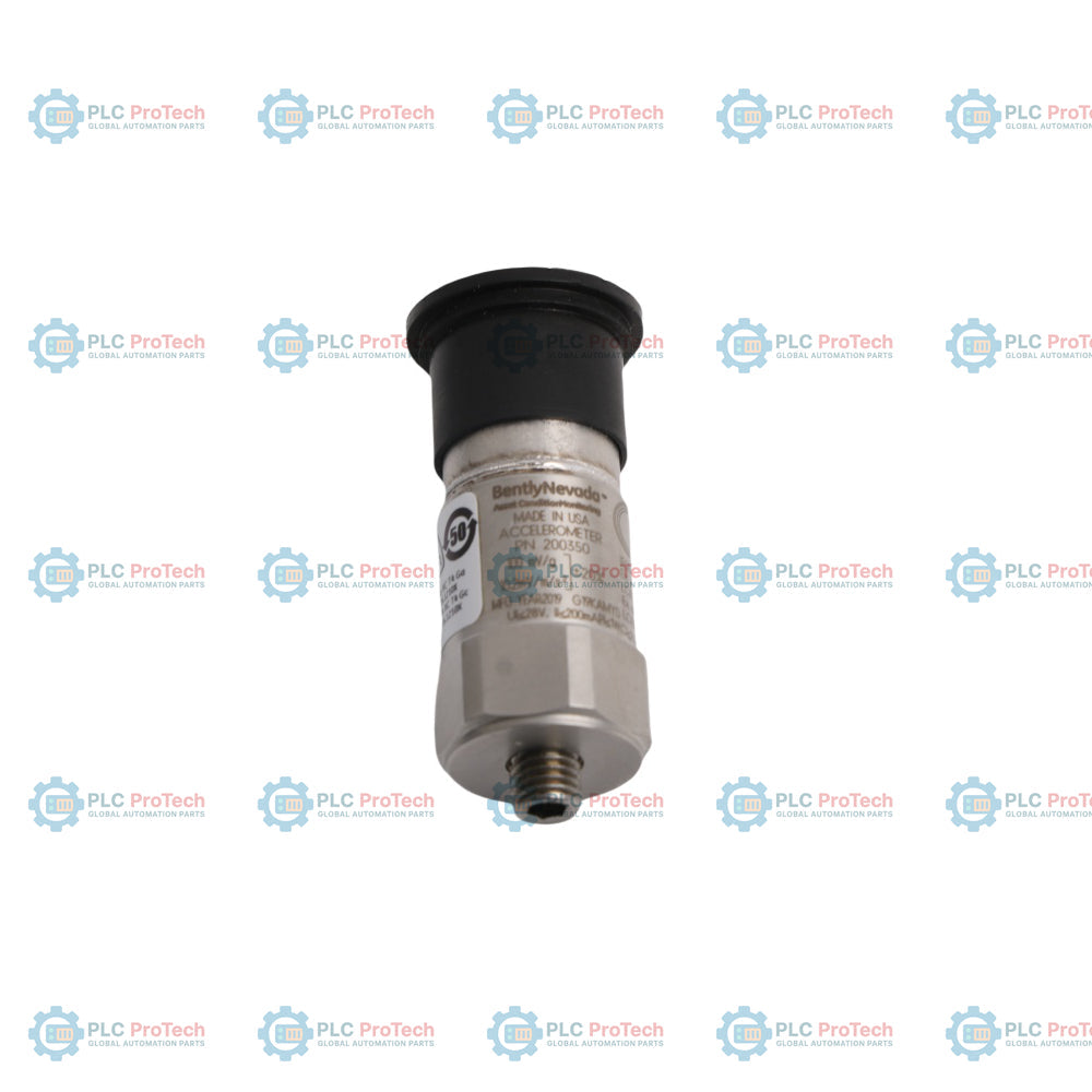
Engineered for distributed machine condition monitoring within the Trendmaster Pro system architecture, the Bently Nevada 200350-12-00-00 functions as a high-reliability seismic transducer. This accelerometer translates physical mechanical vibrations into proportional electrical signals, enabling the early detection of machinery faults such as unbalance, misalignment, and bearing wear. Designed for direct integration with Trendmaster Dynamic Scanning Modules (DSM), the Bently Nevada 200350-12-00-00 provides critical diagnostic data to predictive maintenance systems, reducing unplanned downtime across balance-of-plant assets.
Features
- Seamless compatibility with Bently Nevada Trendmaster Pro scanning networks.
- Robust hermetic sealing to withstand harsh industrial processing environments.
- Wide frequency response optimized for rotating machinery diagnostics.
- Low-profile form factor simplifies installation in restricted spaces.
- Case isolation prevents ground loop interference from motor frames.
Applications
- Balance-of-plant machinery monitoring (fans, blowers, small pumps).
- Industrial electric motor vibration tracking.
- Cooling tower fan gearboxes and structural checks.
- Multi-point automated scanning systems in manufacturing plants.
Technical Specifications
| Parameter |
Value |
| Manufacturer |
Bently Nevada |
| Model/Part Number |
200350-12-00-00 |
| Product Series |
Trendmaster Pro |
| Transducer Type |
Seismic Accelerometer |
| Mounting Option (-12) |
Specific Thread/Stud Configuration |
| Agency Approval (-00) |
Standard (No hazardous area approvals) |
| Connection Option (-00) |
Standard Direct Connection |
| Country of Origin |
United States |
| Shipping Weight (Calculated) |
0.35 kg |
| Package Dimensions (Calculated) |
12.0 x 8.0 x 6.0 cm |
Alternative Models & Compatibility
The Bently Nevada 200350 series accelerometer is specifically matched with the Trendmaster Pro DSM system cabling and processing hardware. Do not attempt to use standard 3-wire or 2-wire IEPE power supplies directly without verifying voltage and bias compatibility with the Bently Nevada processing units, as impedance mismatches will skew vibration amplitudes.
Application Pitfalls & Engineering Notes
When deploying these sensors on high-temperature machinery such as boiler feed pumps, ensure that the ambient operational temperature does not exceed the sensor's maximum thermal rating. Excessive heat will cause permanent sensitivity degradation in the internal piezoelectric element. For cooling tower installations, ensure the cable routing includes drip loops to prevent moisture from pooling at the sensor's connector interface.
Commissioning & Wiring Tips
Always mount the transducer on a flat, clean, bare-metal surface. Any paint, rust, or debris beneath the sensor base acts as a high-frequency dampener, corrupting velocity and acceleration readings. Utilize the specified mounting torque during installation; over-torqueing can distort the internal sensor casing, causing bias voltage errors, while under-torqueing limits frequency response response.
Installation Guidelines
CRITICAL WARNING
Ensure the machinery is fully de-energized and locked out (LOTO) before preparing the mounting surface. Failure to isolate rotating components can result in severe personal injury. Shielded cabling must be continuous and grounded at the system common to prevent electrical noise interference.
1
Prepare a flat, spot-faced surface on the bearing housing perpendicular to the shaft centerline.
2
Apply a thin layer of silicone grease or acoustic couplant to the mounting surface to maximize frequency transfer.
3
Thread the 200350-12-00-00 sensor onto the mounting stud and torque to the manufacturer's specified rating.
4
Connect the Trendmaster system cable, securing the connection boot to prevent fluid and dust ingress.