Présentation du produit
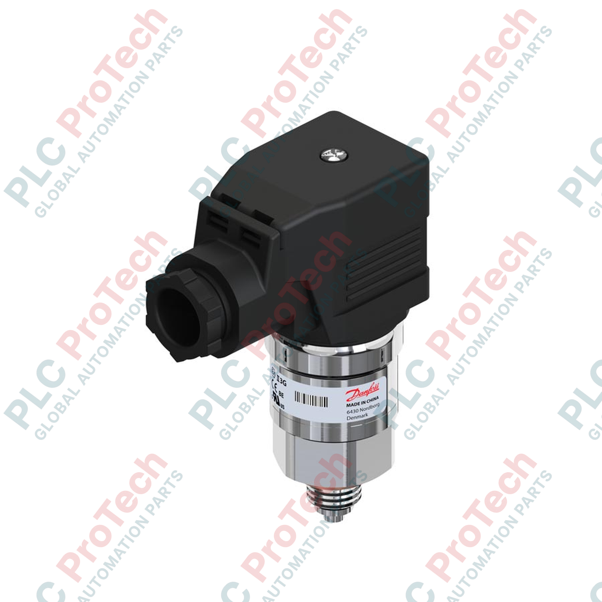
Le 060G5528 (060G5528) est un transmetteur de pression compact à haute précision, approuvé pour le milieu marin, de la série Danfoss MBS 3100. Conçu pour des applications industrielles sévères — notamment les éoliennes offshore, la propulsion marine, les groupes hydrauliques et les circuits de refroidissement des centrales électriques — ce capteur offre une constance éprouvée sur le terrain dans le suivi des vecteurs de fluides à haute pression. En maintenant une boucle de rétroaction analogique 4-20 mA sans erreur vers un automate programmable central (PLC) ou un système de contrôle distribué (DCS), le 060G5528 protège les infrastructures critiques contre les chocs de surpression, la cavitation et les ruptures de tuyauterie, réduisant ainsi significativement le risque d’arrêts système et de fatigue matérielle.
Configuration technique
L’architecture électronique utilise une cellule de mesure piézorésistive logée dans un corps en acier inoxydable résistant aux acides. Ce design à jauge scellée référence les paramètres de pression internes plutôt que les conditions atmosphériques changeantes, ce qui le rend optimal pour des processus jusqu’à 250 bar. L’unité subit un test rigoureux d’autofrettage lors de la production, aboutissant à une capacité de surcharge structurelle de 1500 bar pour résister aux phénomènes sévères de coup de bélier liquide. De plus, le traitement interne du signal applique des seuils de limitation à 3,6 mA et 22,4 mA, permettant aux systèmes de contrôle de différencier immédiatement les données de pression valides des défauts de câblage.
Caractéristiques techniques
| Caractéristique |
Spécification |
| Modèle |
060G5528 |
| Marque |
Danfoss |
| Plage de pression |
0 à 250 bar |
| Sortie boucle |
4-20 mA |
| Précision |
+/- 0,5 % (Typique) / +/- 1,0 % (Max) |
| Surcharge structurelle |
1500 bar |
| Filetage process |
G 1/4 mâle (ISO 1179-2 Forme E) |
| Température de fonctionnement |
-40 à 100 °C |
| Connecteur électrique |
M20 angulaire |
| Indice de protection |
IP65 |
| Poids |
Environ 1,5 kg |
FAQ
Quels sont les avantages d’une référence à jauge scellée par rapport à une jauge standard ?
La jauge scellée référence une cavité interne en vide permanent au lieu d’une ventilation atmosphérique ouverte. Dans les applications haute pression, cela empêche l’entrée d’humidité et l’accumulation de particules derrière la membrane, garantissant la précision lors des nettoyages ou en milieu marin.
Comment les seuils de limitation aident-ils au diagnostic des processus ?
Le capteur limite son signal de sortie. En clampant les valeurs à 3,6 mA et 22,4 mA, la logique du DCS ou du PLC peut isoler instantanément les défauts matériels ou les pannes de boucle des variations valides de pression du processus.
Le point zéro ou l’étendue peuvent-ils être ajustés sur le terrain ?
Non, ce modèle dispose d’une conception entièrement soudée et calibrée en usine sans potentiomètres mécaniques. Cette architecture fixe garantit une stabilité de calibration à long terme et empêche la dérive du signal causée par les vibrations.
Déploiement sur site & protocole de mise en service
-
Montage mécanique : Vissez la connexion process G 1/4 dans un port usiné selon les normes DIN 3852-E ou ISO 1179-2 Forme E. Utilisez une clé calibrée sur les faces hexagonales de 27 mm pour serrer le transmetteur à 35 Nm. Ne jamais faire tourner manuellement la partie supérieure du transmetteur lors de l’installation, car cela pourrait compromettre les joints internes.
-
Câblage électrique : Vérifiez la polarité correcte lors de la connexion de la boucle ; connectez la phase positive à la broche 1 et le retour commun à la broche 2 du connecteur M20. Assurez-vous que le joint en caoutchouc périphérique est bien à plat lors de la fermeture du boîtier pour maintenir l’étanchéité IP65.
-
Atténuation des pulsations : Bien que le capteur dispose d’une haute capacité de surcharge, une exposition constante à la cavitation ou aux coups de bélier rapides finira par provoquer une fatigue. Dans les lignes hydrauliques à haute vitesse ou les systèmes avec vannes à action rapide, intégrez un amortisseur mécanique de pulsations en amont pour protéger la membrane du process.