Profil technique et contrôle dynamique du moteur
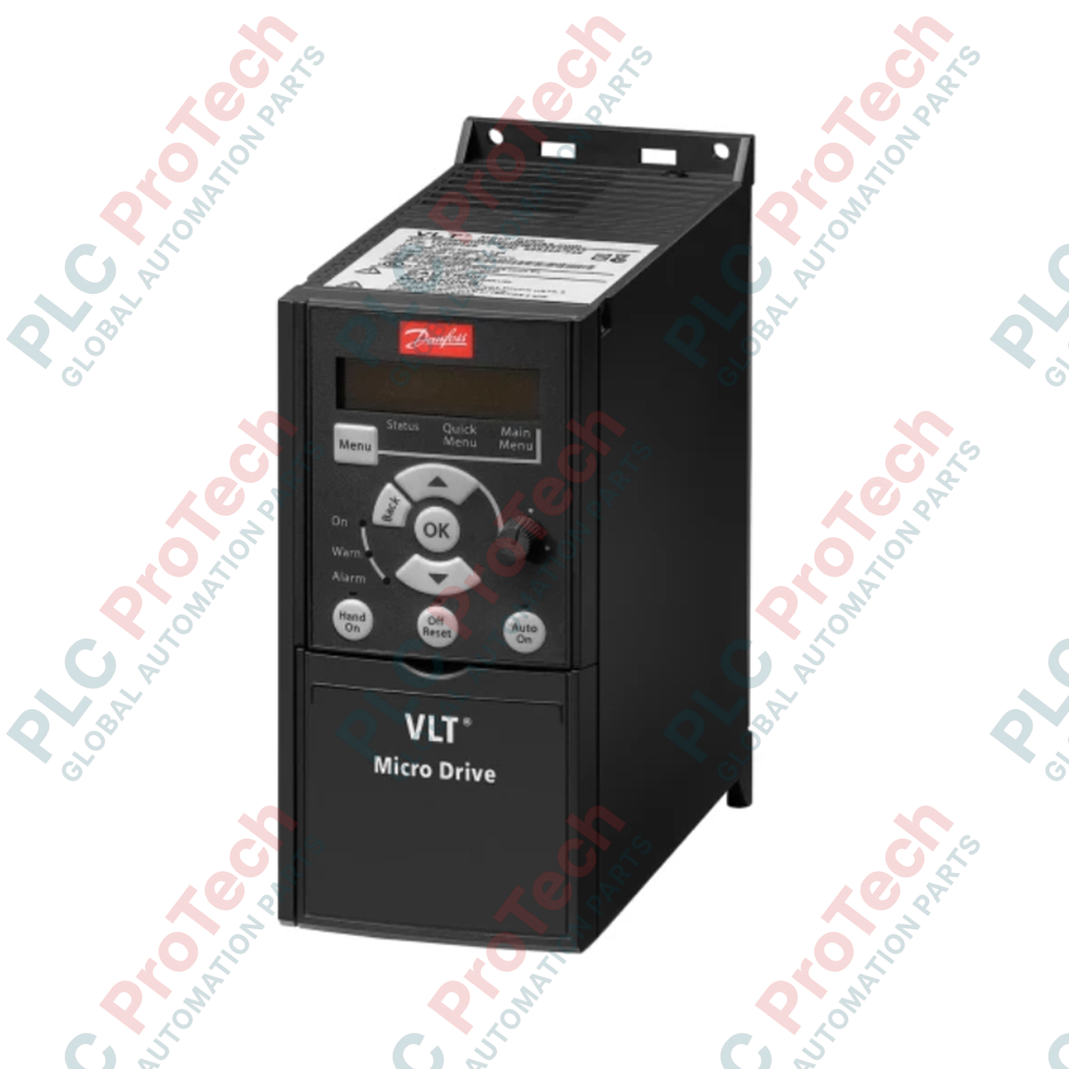
Le 132F0020 (132F0020) est un variateur de fréquence industriel robuste de la série Danfoss VLT Micro Drive FC-051. Conçu pour des armoires de contrôle optimisées en espace, ce variateur de vitesse compact offre un contrôle précis et économe en énergie des moteurs asynchrones triphasés. Il est largement utilisé dans les convoyeurs de manutention, les réseaux de ventilation industrielle, les systèmes de pompage commerciaux automatisés et les lignes de machines OEM spécialisées.
Fonctionnant avec une capacité nominale de 1,5 kW (2,0 HP), le variateur utilise la topologie avancée VVC+ (Voltage Vector Control Plus) pour maintenir une performance exceptionnelle du couple sur l'arbre moteur et une régulation stable de la vitesse même sous des profils de charge fluctuants. En intégrant des capacités locales de maintien en cas de perte de puissance, un assistant automatique de réglage moteur et une protection thermique électronique continue, le variateur minimise l'usure du système, prévient les contraintes mécaniques et assure une disponibilité constante dans les lignes de production à rythme soutenu.
Décomposition du suffixe modèle et schéma structurel
-
FC-051 : Identifie la plateforme principale de la série VLT Micro Drive.
-
P1K5 : Désigne la puissance nominale de sortie électrique de 1,5 kW (2,0 HP).
-
T4 : Établit la configuration de l'alimentation électrique secteur entrante comme triphasée 380-480 VAC.
-
E20 : Désigne la classe d'enveloppe matérielle physique IP20 / Châssis, destinée à un montage en armoire de protection.
-
H3 : Confirme l'intégration d'un filtre RFI haute performance conforme aux normes d'émission électromagnétique Classe A1/B (C1).
-
B : Met en avant l'inclusion d'un module interne de freinage dynamique pour gérer l'énergie régénérative des charges en surcharge.
-
C : Indique que les circuits imprimés internes (PCB) sont protégés par un revêtement conforme pour résister à l'humidité atmosphérique et aux contaminants chimiques particulaires.
Données complètes de performance technique
| Catégorie opérationnelle |
Paramètres techniques documentés |
| Code modèle |
FC-051P1K5T4E20H3BXCXXXSXXX (132F0020) |
| Marque |
Danfoss |
| Origine |
Danemark |
| Profil de courant de sortie |
3,7 A en continu |
| Fréquence d'alimentation secteur |
50/60 Hz |
| Plage de tension de sortie |
0 à 100 % de la tension d'alimentation secteur entrante |
| Capacité de fréquence de sortie |
0 à 200 Hz (mode VVC+ Vectoriel) / 0 à 400 Hz (mode scalaire U/f) |
| Interfaces de contrôle numérique |
5 entrées numériques programmables (logique 0 à 24 VCC) |
| Suivi de référence d'impulsions |
1 interface d'entrée impulsion supportant de 20 à 5000 Hz |
| Interfaces analogiques |
2 entrées analogiques (configurables par logiciel pour boucles de tension ou de courant) |
| Topologie de refroidissement |
Dissipateur thermique intégré à l’arrière avec flux d’air à convection forcée |
| Dimensions physiques |
168 x 75 x 176 mm |
| Poids total à l’expédition |
5,0 kg |
FAQ sur les opérations industrielles sur site et le support
Ce pack variateur inclut-il un panneau de contrôle local ? panneau d’interface ?
Non. Le suffixe de configuration « X » signifie que le variateur autonome 132F0020 n’est pas livré avec un panneau de contrôle local (LCP) préinstallé. Pour la programmation, l’ajustement sur site ou le suivi diagnostic en temps réel, vous devez commander séparément soit le panneau de contrôle VLT LCP 11 (sans potentiomètre), soit le LCP 12 (avec potentiomètre intégré).
Quelle protection opérationnelle spécifique le freinage interne par hacheur offre-t-il ?
Le freinage intégré par hacheur gère l’énergie renvoyée par le moteur lors des cycles de décélération rapide ou lors du freinage de charges à forte inertie. En évacuant cette puissance régénérative via une résistance de puissance externe connectée, le variateur évite les déclenchements par surtension et maintient des profils de rampe de décélération précis.
Pourquoi un variateur de fréquence compact de 1,5 kW pèse-t-il 5,0 kg à l’expédition ?
La masse d’expédition de 5,0 kg reflète un emballage international renforcé. Parce que les variateurs de fréquence industriels robustes contiennent de grands dissipateurs thermiques en aluminium lourds, des condensateurs structurels et des processeurs numériques sensibles, l’unité est emballée dans un film antistatique épais, des inserts moulés amortisseurs épais et un carton extérieur épais pour la protéger contre les chutes et les vibrations mécaniques lors du transport mondial.
Logistique d’installation critique et protocoles de mise en service
-
Montage côte à côte et dégagement thermique : Le design compact du châssis de la série FC-051 permet un montage vertical côte à côte véritable sur rails DIN standard pour maximiser l’espace dans le panneau. Cependant, pour maintenir des courants de convection naturelle adéquats, vous devez conserver un dégagement vertical minimum non obstrué de 100 mm directement au-dessus et en dessous de l’ensemble du ventilateur de refroidissement du variateur.
-
Cheminement séparé des conduits d’entrée et de sortie : Faites passer les câbles d’alimentation secteur entrants (L1, L2, L3) et les lignes d’alimentation moteur en sortie (U, V, W) à travers des conduits industriels complètement séparés. Ne faites jamais circuler les lignes d’alimentation moteur parallèlement aux signaux de commande basse tension, aux fils d’entrée numérique ou aux lignes de communication afin d’éviter les diaphonies électromagnétiques.
-
Normes de blindage et de mise à la terre des câbles moteur : Connectez toujours le variateur au moteur en utilisant un câble blindé en cuivre tressé de haute qualité et continu. Terminez complètement la surface du blindage aux deux extrémités avec des pinces de mise à la terre métalliques à faible impédance — une sur la plaque de blindage du châssis du boîtier du variateur et l’autre directement sur le boîtier de bornes du moteur — pour supprimer les interférences radiofréquences (RFI) à haute fréquence.