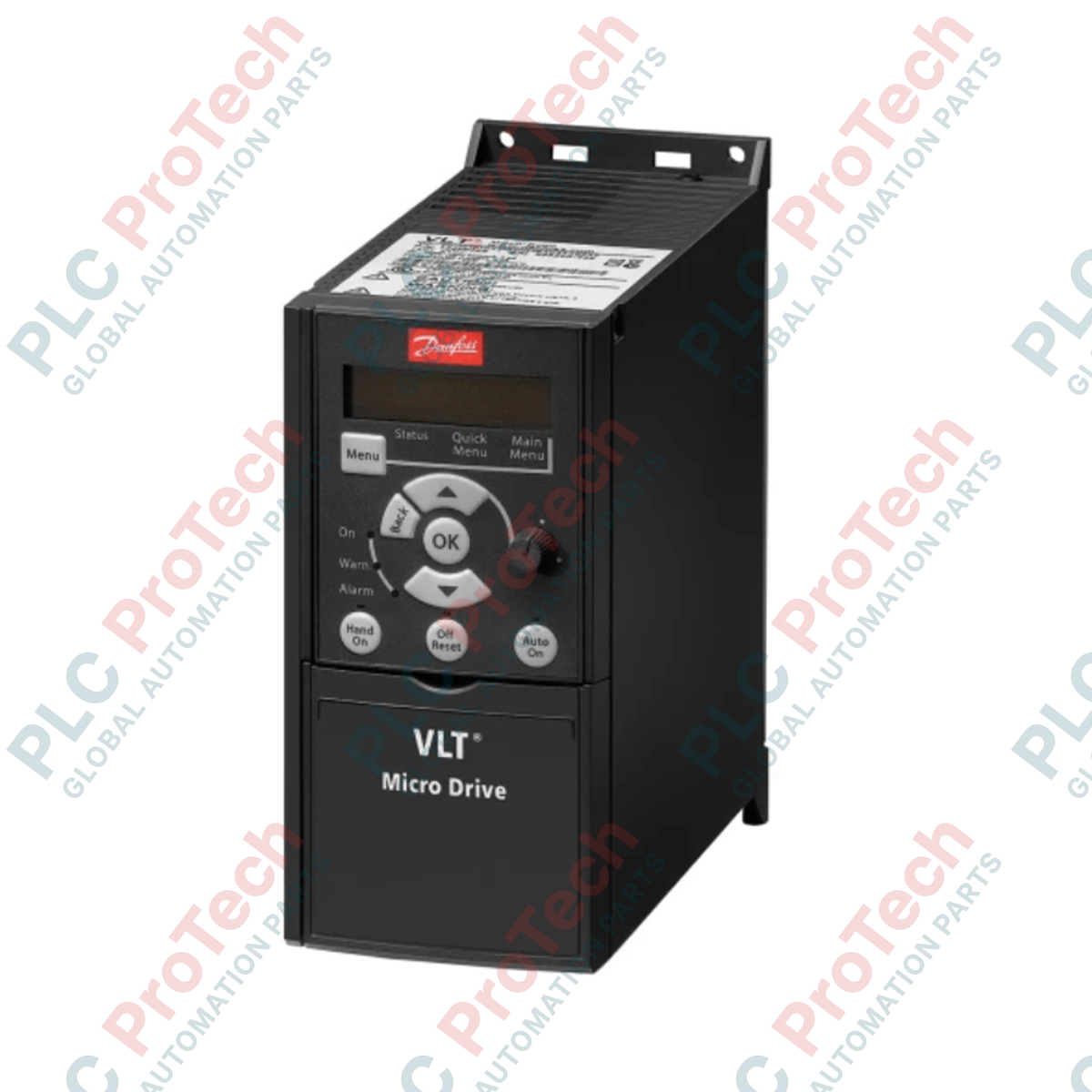
Présentation du produit
Le Danfoss 132F0022 (FC-051P2K2T4E20H3BXCXXXSXXX) VLT Micro Drive est un variateur de fréquence robuste conçu pour répondre aux exigences strictes de l'automatisation industrielle moderne. Qu'il soit utilisé dans des systèmes automatisés de manutention de matériaux, le contrôle de pompes pour le traitement municipal de l'eau ou des applications de convoyeurs en fabrication, ce variateur constitue un élément clé pour stabiliser la performance du moteur et prolonger la durée de vie mécanique. En utilisant un contrôle de flux VVC+ à haute efficacité, l'appareil minimise la distorsion harmonique et le stress thermique sur les enroulements du moteur, réduisant ainsi efficacement les arrêts imprévus. Son architecture compacte, basée sur un châssis, est optimisée pour une intégration à haute densité dans les armoires de commande, offrant aux ingénieurs une solution fiable pour une régulation précise de la vitesse dans des boucles de processus critiques où l'espace et la disponibilité opérationnelle sont essentiels.
Décomposition du suffixe
Le code de commande 132F0022 suit la nomenclature structurée de Danfoss pour la série VLT Micro Drive FC-051. Le segment "P2K2" indique une puissance nominale de 2,2 kW (3,0 HP). La classification "T4" désigne une capacité d'entrée triphasée adaptée aux réseaux 380-480 VAC. Le "E20" correspond à un boîtier classé IP20, garantissant que les composants internes restent protégés dans des environnements d'armoire propres. Les filtres RFI intégrés "H3" assurent une compatibilité électromagnétique de classe A1/B (C1), essentielle pour minimiser les interférences avec les instruments sensibles. La désignation "B" confirme la présence d’un freinage dynamique avec un hacheur de frein interne, tandis que le code "C" indique un revêtement conforme appliqué en usine sur le circuit imprimé interne, protégeant la carte contre l’humidité et la contamination environnementale.
Caractéristiques techniques
| Caractéristique |
Spécification |
| Modèle |
132F0022 |
| Marque |
Danfoss |
| Origine |
Danemark / Fabrication mondiale |
| Poids |
5 kg |
| Dimensions (L x W x H) |
16,8 cm x 7,5 cm x 17,6 cm |
| Température de fonctionnement |
-10 à 50 °C |
| Puissance nominale |
2,2 kW (3,0 HP) |
| Courant de sortie |
5,3 A |
| Tension d’alimentation |
380 - 480 VAC (triphasé) |
| Entrées numériques |
5 (0-24 VDC) |
| Entrées analogiques |
2 |
| Modes de contrôle |
VVC+ et U/f |
FAQ
Le 132F0022 peut-il fonctionner sans LCP ?
Oui, le variateur est conçu pour fonctionner de manière autonome une fois programmé, bien qu’un LCP détachable ou un logiciel PC soit nécessaire pour la configuration initiale et le paramétrage.
Quelle est la principale différence entre les modes de contrôle VVC+ et U/f sur ce variateur ?
Le VVC+ (contrôle vectoriel de tension) offre une meilleure réponse en couple et une précision de vitesse supérieure pour les applications moteurs standard, tandis que le mode U/f est généralement réservé aux applications spéciales comme le fonctionnement parallèle de moteurs ou le contrôle moteur à haute fréquence.
Comment le revêtement conforme prolonge-t-il la durée de vie du variateur ?
Le suffixe "C" indique un circuit imprimé revêtu, ce qui empêche l’oxydation et la dégradation des voies conductrices lorsque le variateur est installé dans des environnements à forte humidité ou exposés à des traces de polluants chimiques atmosphériques.
Puis-je remplacer ce variateur par une autre série en cas d’obsolescence ?
Bien que le VLT Micro Drive FC-051 soit une unité standard, tout remplacement doit vérifier la puissance nominale, la classe de tension et l’encombrement physique ; consultez le manuel technique pour assurer la compatibilité avec votre logique de commande existante.
Consignes d’installation et d’utilisation
-
Gestion thermique et dégagement : Pour une dissipation thermique optimale, maintenez un dégagement vertical minimum de 100 mm au-dessus et en dessous de l’unité. Évitez d’installer le variateur à proximité directe de sources de chaleur importantes telles que les résistances de freinage ou les échangeurs thermiques afin de prévenir les déclenchements intempestifs dus à des défauts de surchauffe.
-
Pratiques de blindage CEM : Pour garantir la conformité aux normes RFI et éviter les parasites, utilisez des câbles blindés pour les connexions moteur. L’écran doit être raccordé au châssis du variateur à l’aide de presse-étoupes métalliques ou de colliers assurant une connexion haute fréquence à 360 degrés. Ne regroupez jamais les câbles d’alimentation avec les fils de signal basse tension dans le même chemin de câble.
-
Vérification de sécurité : Avant toute intervention sur le câblage des bornes ou dépannage, assurez-vous que l’alimentation secteur est déconnectée et attendez au moins 4 minutes pour que les condensateurs du bus DC interne se déchargent à un niveau de tension sûr. Vérifiez toujours l’état de la LED de charge interne avant de toucher le bornier.