Présentation & valeur technique
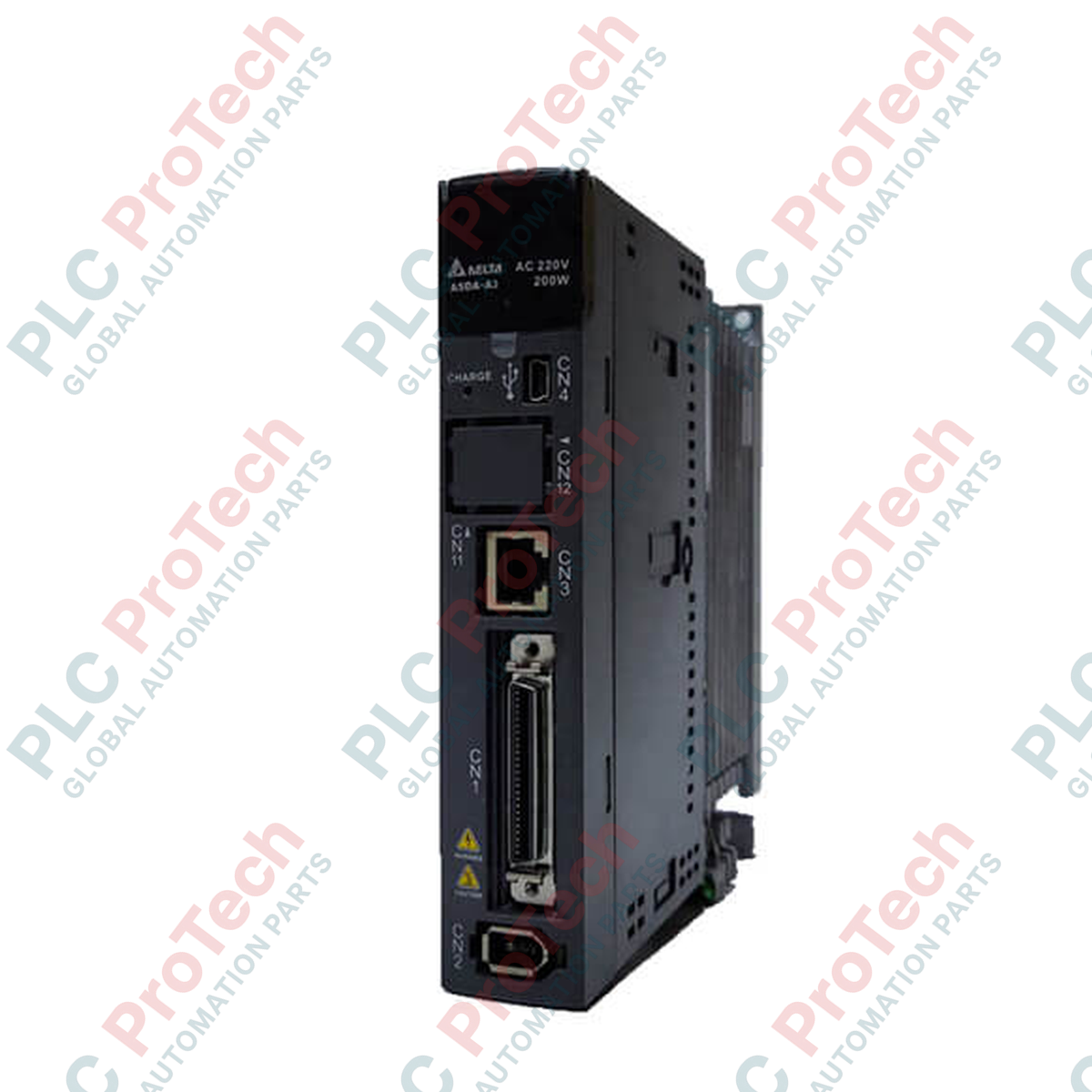
Le ASD-A3-0221-M (ASDA30221M) est un servomoteur AC haute performance de 200 W conçu pour des architectures de contrôle de mouvement critiques en sécurité et à large bande passante dans la plateforme Delta ASDA-A3. Développé pour répondre aux exigences rigoureuses de l'assemblage électronique de précision, de l'emballage de semi-conducteurs, de l'automatisation médicale et des systèmes multi-axes de pick-and-place à grande vitesse, ce variateur compact optimise significativement l'efficacité des machines.
En offrant une réponse avancée de boucle de contrôle ainsi que des fonctions de sécurité Safe Torque Off (STO) intégrées, l'unité garantit une protection maximale de l'opérateur sans compromettre la disponibilité de la production. L'intégration d'un support de retour haute résolution et de fonctions de suppression de résonance mécanique atténue efficacement les vibrations structurelles, ce qui se traduit par des temps de stabilisation rapides et un positionnement fiable sans erreur.
Configuration système & architecture réseau
La topologie électrique de ce variateur permet une distribution d'énergie polyvalente, acceptant des entrées en courant alternatif monophasé ou triphasé 220 V. Classé comme variante de type « M », cette plateforme matérielle est optimisée pour les réseaux avancés de contrôle de mouvement distribué, avec une capacité native de communication CANopen ainsi que des interfaces série RS-485 Modbus standard.
Pour les conceptions de systèmes localisés ou hérités, le variateur conserve une entrée train d'impulsions (PT) à haute vitesse, des routines internes de séquençage du registre de position (PR) et des boucles de contrôle de tension analogique précises. De manière cruciale, le variateur dispose d'entrées de retour double encodeur pour faciliter un contrôle en boucle fermée complet directement depuis le côté charge, ainsi qu'un moteur de came électronique intégré (E-CAM) pour des profils maître-esclave complexes.
Spécifications matérielles
| Paramètre |
Détails des spécifications |
| Modèle |
ASD-A3-0221-M |
| Marque |
DELTA |
| Origine |
Taïwan |
| Puissance de sortie nominale |
200 W |
| Infrastructure d'alimentation |
220 VAC, monophasé / triphasé |
| Formats de contrôle |
Train d'impulsions (PT), registre de position (PR), tension analogique |
| Communication bus |
CANopen, RS-485 Modbus RTU |
| Matériel de sécurité intégré |
Conformité Safe Torque Off (STO) SIL2 / PL d |
| Architecture de boucle |
Suivi en boucle fermée complète (entrée encodeur secondaire via CN5) |
| Profils de mouvement |
Synchronisation par came électronique interne (E-CAM) |
| Indice de protection du boîtier |
IP20 |
| Dimensions |
155 mm x 45 mm x 156 mm |
| Poids |
0,84 kg (Poids d'expédition : 3,0 kg avec emballage renforcé pour le transport) |
| Plage de température ambiante |
0 à 55 °C |
Questions techniques & dépannage
-
Comment fonctionne la fonction intégrée Safe Torque Off (STO) lors d'une condition d'arrêt d'urgence ?
La fonction STO interrompt directement l'alimentation des transistors de sortie IGBT internes. Cette séparation au niveau mécanique empêche l'étage onduleur de générer le champ magnétique tournant nécessaire pour produire le couple moteur. Parce qu'elle contourne les couches logicielles du microprocesseur, elle garantit un état moteur sûr et non alimenté sans nécessiter la coupure du contacteur principal AC en amont, permettant une récupération plus rapide du système.
-
Quel alignement de paramètres est requis pour basculer entre le contrôle CANopen et le mode standard Train d'impulsions ?
La sélection du mode de contrôle est déterminée par des paramètres internes situés dans le groupe de paramètres principal (généralement P1-01). La configuration de ce registre définit si le chemin de commande interne référence le tampon de communication haute vitesse ou les entrées optocoupleurs physiques sur le connecteur CN1. Un cycle d'alimentation est nécessaire après modification des paramètres pour réallouer la logique interne du processeur.
-
Quelles mesures atténuent les erreurs de suivi de position lors de la mise en œuvre de la configuration en boucle fermée complète ?
Lors de la fermeture de la boucle autour d'une règle linéaire externe, assurez-vous que la résolution de la règle est correctement définie dans les paramètres du rapport de démultiplication électronique du variateur. Si la déviation de suivi des doubles encodeurs dépasse le seuil prédéfini dans les registres de surveillance, le variateur déclenchera une erreur de déviation de position pour éviter une dérive mécanique causée par le jeu ou le glissement de courroie.
Mise en service sur site et protocoles de sécurité
Exigences de câblage de la boucle de sécurité STO
Lors de l'interface des entrées double canal STO via le connecteur de sécurité désigné, les deux canaux doivent être alimentés par des sorties de sécurité 24 VDC indépendantes provenant d'un relais de sécurité certifié ou d'un automate de sécurité. Le retrait du cavalier d'usine sans établir le câblage double canal correct inhibera définitivement l'étage de puissance, empêchant l'exécution de l'état prêt servo.
Normes de terminaison du bus de terrain CANopen
Pour maintenir une transmission fiable des paquets de données sur le réseau CANopen, installez une résistance de terminaison en film métallique de 120 Ohms entre les lignes de signal CAN_H et CAN_L aux deux extrémités physiques du segment réseau. Utilisez des câbles CAN blindés à paires torsadées dédiés avec une impédance caractéristique de 120 Ohms. Le blindage extérieur doit être fixé au panneau arrière métallique de chaque châssis de variateur pour détourner les bruits de masse haute fréquence loin des puces du transceiver.
Réglage dynamique et suppression des vibrations
Utilisez les outils d'auto-réglage dans l'environnement ASDA-Soft pour calculer le rapport exact d'inertie de charge. Si l'assemblage mécanique présente un bruit acoustique haute fréquence ou une résonance lors de profils d'accélération élevés, activez le système interne de filtrage en entaille. Le variateur dispose de filtres en entaille automatiques qui analysent la rétroaction de la boucle de courant, isolent les pics de résonance et injectent une atténuation de phase pour stabiliser le trajet de mouvement sans dégrader la réactivité globale du système.