Description
Engineered to meet the demanding requirements of high-performance motion control applications, the Delta Electronics ASD-A2-3023-F is a 3.0 kW digital servo drive operating within the high-precision ASDA-A2 Series. This unit provides precise torque, speed, and position control, utilizing advanced closed-loop algorithms to deliver exceptional dynamic response. Designed with an F-type configuration, this drive integrates seamlessly with Delta's high-speed DMCNET communication protocol and supports full-closed loop control to eliminate mechanical backlash in demanding industrial environments.
Features
-
Full-Closed Loop Control: Direct feedback interface for secondary linear scales or rotary encoders to minimize mechanical transmission errors.
-
High-Speed Communication: Equipped with native DMCNET interface for synchronized multi-axis motion network configurations.
-
Advanced Vibration Suppression: Built-in automatic high-frequency notch filters and low-frequency vibration dampers to stabilize mechanical systems.
-
Electronic Cam (E-CAM): Integrated E-CAM function supporting up to 720 master-slave points for flying shear, rotary cut, and complex profiling curves.
-
Dual-Loop Feedback: Enhances position loop stability and guarantees robust positioning accuracy down to the sub-micron level.
Applications
- High-speed packaging and continuous rotary sealing machinery.
- Multi-axis CNC machining centers, precision engraving, and metal cutting systems.
- Semiconductor manufacturing equipment and automated pick-and-place gantry systems.
- Textile machinery and high-speed tension-controlled winding applications.
Technical Specifications Table
| Parameter |
Specification Value |
| Manufacturer |
Delta Electronics |
| Model Designation |
ASD-A2-3023-F |
| Product Series |
ASDA-A2 Series |
| Rated Output Power |
3.0 kW |
| Input Voltage / Phase |
220V AC, 3-Phase |
| Model Type / Communication |
F Type (DMCNET Interface) |
| Control Modes |
Position, Speed, Torque, DMCNET Protocol Control |
| Cooling Method |
Natural Air / Fan Cooling |
| Device Weight |
2.89 kg |
| Shipping Weight (Calculated) |
6.0 kg |
Connections and Interfaces
| Connector / Terminal |
Functional Assignment |
| R, S, T |
Main AC Power Supply Input (220V 3-Phase) |
| U, V, W |
Servo Motor Power Output Terminals |
| P+, D, C |
Regenerative Resistor Connections (Internal / External options) |
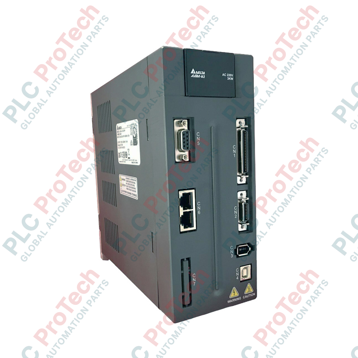
| CN1 |
I/O Control Interface (Digital Inputs, Digital Outputs, Analog Monitors) |
| CN2 |
Motor Feedback Encoder Interface Connection |
| CN5 |
Full-Closed Loop Interface (External Scale Input) |
Empirical Engineering Insights
Alternative Models & Compatibility
The ASD-A2-3023-F is specifically optimized for high-speed DMCNET topologies. If your application relies on CANopen or standard pulse/train communication, look to the -M (CANopen) or -B (Standard Pulse/Analog) variants. Ensure matching encoder resolutions when paring this drive with ECMA-F11830 or ECMA-E11830 series 3.0 kW motors to prevent internal commutation errors on startup.
Application Pitfalls & Engineering Notes
Under heavy cycling or high-inertia decelerations, the internal regenerative resistor capacity of the 3.0 kW drive can be quickly exceeded, triggering an AL005 (Overvoltage) fault. For operations featuring rapid deceleration ramps, always calculate energy dissipation and install an appropriately rated external regenerative resistor across the P+ and D terminals while removing the jumper between D and C.
Commissioning & Wiring Tips
Because the DMCNET interface relies on high-speed serial packets, run all communication cables inside dedicated, shielded conduits separated from the high-voltage motor power lines (U, V, W) by at least 30 cm. Ground loop currents can disrupt encoder readings on CN2; always verify that the motor frame is grounded directly to the drive's protective earth terminal using a heavy-gauge copper strap.
Installation Guidelines
CRITICAL WARNING: Hazardous voltage levels remain present in the drive's internal DC bus capacitors for up to 10 minutes after main power is disconnected. Prior to performing any service, installation, or terminal wiring, isolate the AC main line and verify with a calibrated multimeter that the voltage across terminals P+ and - has discharged below 36V DC. Failure to comply can result in severe electrical shock or death.
1
Mount the drive vertically on a flat, non-combustible metal panel to optimize natural convection. Keep at least 50 mm of clear space above and below the cooling fans for adequate ventilation.
2
Ensure the 220V 3-phase incoming power lines are protected by a high-interrupting capacity circuit breaker and an electromagnetic contactor connected to the emergency stop circuit.
3
Connect the motor power cable securely to U, V, and W. Under no circumstances should 3-phase main power be applied to these output terminals, as this will result in immediate catastrophic destruction of the internal IGBT module.