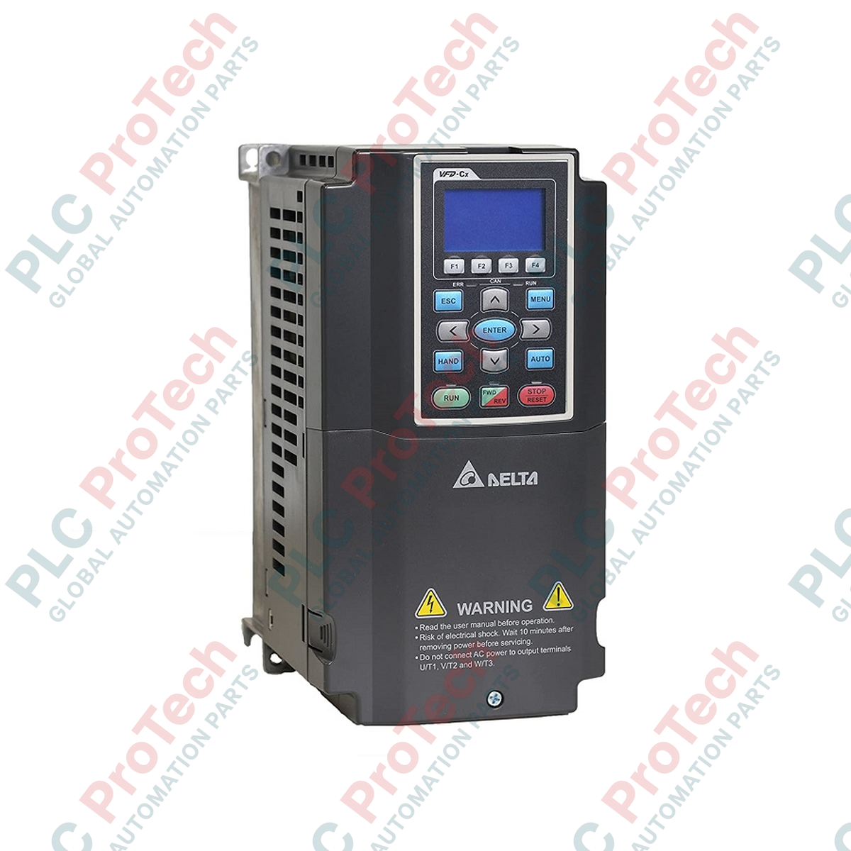
Description
Designed to operate as a high-performance field-oriented control vector drive, the Delta Electronics VFD055C43A offers robust motor control capabilities within the professional-grade C2000 Series. This unit is built to manage both standard induction motors and high-efficiency permanent magnet motors, providing adaptable dual-rating performance characteristics suited for heavy-duty industrial automation architectures. By integrating a built-in 10,000-step PLC and dynamic energy-saving algorithms, this variable frequency drive delivers precise speed, torque, and position control while maintaining exceptional grid-side electrical efficiency.
Features
-
Dual-Duty Rating: Seamlessly switch between Normal Duty (ND) and Heavy Duty (HD) profiles depending on process overload requirements.
-
Advanced FOC Vector Control: Supports closed-loop encoder feedback for absolute positioning and high-torque performance at zero speed.
-
Modular Hardware Architecture: Hot-swappable keypad, removable terminal blocks, and plug-and-play fieldbus expansion cards.
-
Embedded PLC Functionality: Integrated 10k-step program execution capacity eliminates the need for external micro-PLCs in simple OEM systems.
-
Built-in DC Choke: Reduces total harmonic distortion (THD) and mitigates standard line impedance disruptions.
Applications
-
Constant Torque Loads: Ideal for industrial extruders, heavy-duty conveyors, and high-inertia reciprocating machinery.
-
Fluid Management: Precise pressure and flow regulation for high-capacity centrifugal pumps and positive displacement blowers.
-
Material Handling: High-speed gantry control, hoist units, and automated warehousing systems requiring rapid acceleration ramp profiles.
-
Metalworking and CNC: Spindle drive control on standard milling machines and high-speed precision grinders.
Technical Specifications
| Technical Parameter |
Value / Specification |
| Manufacturer |
Delta Electronics |
| Model Number |
VFD055C43A |
| Series Name |
C2000 Series (Variable Frequency Drive) |
| Input Phase / Voltage |
3-Phase 460V AC (Nominal) |
| Normal Duty (ND) Capacity |
10 kVA |
| Normal Duty Output Current |
12 A |
| Normal Duty Motor Rating |
5.5 kW (7.5 HP) |
| Normal Duty Max Frequency |
0.00 to 599.0 Hz |
| Normal Duty Carrier Frequency |
2 to 15 kHz (Default 8 kHz) |
| Heavy Duty (HD) Capacity |
9.6 kVA |
| Heavy Duty Output Current |
11 A |
| Heavy Duty Motor Rating |
4.0 kW (5 HP) |
| Heavy Duty Max Frequency |
0.00 to 300.0 Hz |
| Heavy Duty Carrier Frequency |
2 to 6 kHz (Default 2 kHz) |
| Physical Net Weight |
2.6 kg |
| Shipping Weight (Calculated) |
4.0 kg |
| Package Dimensions (Calculated) |
310 mm x 200 mm x 210 mm |
Alternative Models & Compatibility
The VFD055C43A features standard IP20 enclosure ratings and is the recommended direct path of replacement for legacy Delta VFD-B series drives of comparable frame outputs. When upgrading older field configurations, verify control terminal mapping differences; the C2000 features modern, push-in spring terminal configurations for logic signals compared to older screw-terminal standard blocks.
Application Pitfalls & Engineering Notes
When running the drive in Heavy Duty mode within enclosed electrical cabinets, pay strict attention to thermal dissipation guidelines. A minimum clearance space of 50mm on both lateral sides and 120mm on vertical boundaries is required to prevent heat-trapping and consequent over-temperature trips (Fault Code: oH1). If operating on high-inertia or dynamic braking cycles, an external dynamic braking resistor with a minimum resistance value of 80 Ohms must be wired to prevent DC bus overvoltage faults (Fault Code: ov).
Commissioning & Wiring Tips
To avoid serial communication timeout interruptions, isolate the control and communication wiring (e.g., Modbus RS-485 network lines) from the primary 460V power input and motor output conductors. Run control signals in separate grounded metallic conduits. If implementing closed-loop vector control, use twisted-pair shielded cables for PG feedback lines, connecting the shield braid exclusively to the ground terminal on the drive side to prevent electromagnetic noise coupling.
Installation Guidelines
CRITICAL WARNING: Hazardous voltages remain present on the internal capacitor bank for at least ten minutes after incoming physical power is disconnected. Prior to mounting or executing any terminal connections, confirm main power isolating breakers are locked out and verify that DC bus voltages (measured across terminals +2/B1 and -) have bled down to 0V.
1
Mount the drive unit vertically on a rigid, vibration-resistant, non-combustible surface to ensure adequate thermal airflow.
2
Connect incoming 3-phase mains supply line power to terminals R/L1, S/L2, and T/L3 via certified semiconductor fusing.
3
Wire motor power leads to terminals U/T1, V/T2, and W/T3. Earth ground the motor frame directly to the designated drive ground terminal.
4
Execute standard parameter auto-tuning (specifically Parameter 05-00 for motor profile parameters) with the motor disconnected from physical mechanical loads.