Description
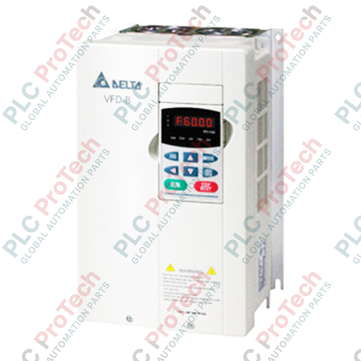
Engineered to deliver highly reliable speed and torque control for industrial induction motors, the Delta Electronics VFD110B23A is a robust vector AC motor drive within the trusted VFD-B series. This 11 kW (15 HP) inverter functions as a NEMA 1 general-purpose motor controller, accommodating both open-loop and closed-loop vector control architectures. Operating on a 3-phase 200-240V input supply, it delivers a continuous output current of 49 Amps and supports an output frequency span from 0.1 to 400 Hz. Built-in Modbus communication interfaces seamlessly with centralized PLC control systems, while the modular design allows for expanded fieldbus integration via optional communication cards.
Key Features
-
Dual Control Profiles: Supports adjustable V/f curve tuning alongside high-performance sensorless vector and closed-loop vector control.
-
Multi-Step Speed Sequencing: Configurable 16-step speed progression and 15-step preset process control paths.
-
Integrated Process Regulation: Built-in PID feedback control loop simplifies external instrumentation configuration.
-
Dynamic Protection Systems: Automatic torque boost, slip compensation, and customizable overload thresholds preserve system safety.
-
Industrial Communications: Built-in Modbus serial network connection with transmission speeds up to 38400 bps.
Applications
-
Conveyor and Material Handling: Constant torque profiles ensure smooth, controlled starting and positioning under heavy loads.
-
Pumping and Ventilation Systems: Utilizes energy-saving V/f curves and PID sleep/wake functions for flow control.
-
Extruders and Mixers: High starting torque capabilities prevent stalling during high-viscosity process start-ups.
-
Machine Tool Spindles: Exact frequency output up to 400 Hz delivers precise speed control for milling and turning machinery.
Technical Specifications
| Parameter |
Specification Value |
| Manufacturer |
Delta Electronics |
| Model Number |
VFD110B23A |
| Product Series |
VFD-B Series |
| Nominal Motor Power |
11 kW / 15 HP |
| Input Voltage / Phase |
3-Phase 200V to 240V AC (50/60 Hz) |
| Output Voltage / Phase |
3-Phase 0V to 240V AC (Proportional to Input) |
| Rated Output Current |
49 Amps |
| Output Frequency Range |
0.1 to 400 Hz |
| Control Methodology |
V/f Control, Sensorless Vector Control (SVC), Closed-Loop Vector (with PG Card) |
| Communication Interface |
Built-in RS-485 Modbus (up to 38400 bps via RJ11) |
| Optional Network Support |
DN-02 (DeviceNet), LN-01 (LonWorks), PD-01 (Profibus DP) |
| Enclosure Rating |
IP20 / NEMA 1 |
| Operating Temperature |
-10 to 40 degC (Non-condensing) |
| Shipping Weight |
14.0 kg |
| Dimensions (Calculated) |
320 mm x 200 mm x 190 mm (Frame D Profile) |
Connections and Interfaces
| Terminal Code |
Functional Assignment |
| R/L1, S/L2, T/L3 |
3-Phase AC Main Power Input (200-240V) |
| U/T1, V/T2, W/T3 |
3-Phase Variable AC Output to Motor |
| +1, +/B1 |
DC Reactor Connection Terminals (Jumpered by default) |
| +/B1, B2 |
Dynamic Braking Resistor Terminals |
| Ground (PE) |
Protective Earth Grounding Terminals |
Empirical Engineering Insights
Alternative Models & Compatibility
The VFD110B23A serves as a drop-in replacement for legacy VFD-B drives of matching frame specifications. Note that upgrading older control loops utilizing analog feedback may require specific module alignment parameters. If integrating into high-speed architectures requiring 2000 Hz operation, ensure that your device has been factory programmed for high-frequency output, as standard firmware caps output frequency at 400 Hz.
Application Pitfalls & Engineering Notes
Operating an 11 kW drive at low speeds under constant torque loads can cause significant heat accumulation in the connected motor. Ensure the motor is equipped with an independent cooling fan (force-ventilation) if continuously running below 20 Hz. Additionally, pay close attention to the installation clearing distances; a minimum of 150 mm vertical clearance is required above and below the chassis to prevent local ambient temperatures from exceeding the 40 degC limit within high-density control panels.
Commissioning & Wiring Tips
When utilizing sensorless vector control (SVC), execute a motor auto-tune with the load uncoupled from the shaft. This allows the drive to precisely map stator resistance and inductance metrics, eliminating erratic torque behavior at startup. For Modbus serial networks, always terminate the final drive node with a 120-ohm resistor across the RS-485 differential lines to eliminate data reflections that can trigger communication timeout faults (CFe).
Installation Guidelines
CRITICAL WARNING: HIGH VOLTAGE SAFETY
Isolate all primary AC power inputs before attempting installation or maintenance. Internal bus capacitors retain dangerous voltages. Wait at least 10 minutes after disconnecting supply power and verify that the internal DC bus voltage has discharged below 24V DC using a digital multimeter prior to working on any electrical connections.
1
Physical Mounting: Secure the drive vertically to a flat, flame-resistant metal backplate to facilitate proper convective cooling flow.
2
Power Connections: Route 3-phase input lines to R/L1, S/L2, and T/L3. Connect motor lines to U/T1, V/T2, and W/T3. Apply recommended torque settings to terminal screws.
3
Control & Shield Grounding: Terminate control signal wiring shields at the drive's control ground terminal only. Maintain separate routing channels for control cables and high-power motor lines to reduce electromagnetic interference.