Description
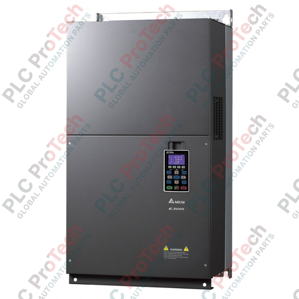
Engineered for high-performance field-oriented control in heavy industrial automation systems, the Delta Electronics VFD1600C43A-00 is a premium three-phase AC motor drive belonging to the high-reliability C2000 Series. This variable frequency drive features dual-rating capabilities, allowing it to seamlessly adapt to both Normal Duty (ND) and Heavy Duty (HD) operational modes. Supporting an input voltage span of 323 to 528 VAC at 47 to 63 Hz, it achieves an optimal efficiency rating of 98.2%. Housed in a durable Frame Size F physical enclosure, this module integrates advanced velocity, torque, and position control algorithms, ensuring maximum motor shaft efficiency and reliable power management across heavy-duty industrial machinery.
Key Features
-
Dual-Rating Performance: Capable of driving up to 160 kW in Normal Duty (pump/fan) and 132 kW in Heavy Duty (constant torque) configurations.
-
High Operational Efficiency: Minimizes thermal loss and energy consumption with a verified 98.2% efficiency design.
-
Robust Voltage Handling: Designed for fluctuating power networks, accommodating input ranges from 323 to 528 Volts AC.
-
Advanced Vector Control: Supports closed-loop PM and IM motor control alongside standard V/f operations.
-
Integrated Fieldbus Capabilities: Features native communication options to integrate directly with factory-level industrial networks.
Applications
- High-capacity industrial water pumps and municipal aeration systems.
- Large-scale HVAC fans and industrial ventilation blowers.
- Constant torque extruders, mixers, and industrial kneaders.
- Material handling conveyor lines, overhead cranes, and hoist systems.
- Industrial air compressors and gas booster stations.
Technical Specifications
| Parameter |
Normal Duty (ND) Value |
Heavy Duty (HD) Value |
| Applicable Motor Output (kW) |
160 kW |
132 kW |
| Applicable Motor Output (HP) |
215 HP |
175 HP |
| Rated Output Current (A) |
310 A |
295 A |
| Rated Output Capacity (kVA) |
247 kVA |
235 kVA |
| Input Current (A) |
300 A |
285 A |
| General System Specifications |
| Operating Voltage Range |
323 to 528 Volts AC (3-Phase) |
| Frequency Tolerance |
47 to 63 Hz |
| Drive Efficiency |
98.2% |
| Frame Size |
Frame F |
| Manufacturer |
Delta Electronics |
| Physical Dimensions (L x W x H) |
42 cm x 30 cm x 80 cm |
| Net Unit Weight |
86.5 kg |
| Shipping Weight |
89.0 kg |
Connections and Interfaces
| Terminal Group |
Interface Type |
Functional Assignment |
| R/L1, S/L2, T/L3 |
Three-Phase AC Input |
Main power grid supply inputs. |
| U/T1, V/T2, W/T3 |
Three-Phase Motor Output |
Variable frequency output connections to the motor stator. |
| Digital Inputs |
Multi-Function Terminals (MI1 to MI8) |
Configurable sequence controls, emergency stop, and reset circuits. |
| Analog Inputs |
AVI (0-10V) / ACI (4-20mA) |
External frequency reference and feedback channel loop inputs. |
| Grounding |
PE Terminal |
Protective earth connection point to prevent chassis shock hazards. |
Alternative Models & Compatibility
The VFD1600C43A-00 is highly backwards-compatible with standard parameters from older Delta VFD-F and VFD-B series drives, provided control loops are mapped to identical digital/analog logical terminals. When replacing older systems, ensure firmware parameters are re-verified, especially when utilizing closed-loop vector cards or optional network interfaces like MODBUS TCP or EtherNet/IP adapter modules.
Application Pitfalls & Engineering Notes
When operating Frame F units in enclosed cabinets, ensure continuous thermal management. Because the drive generates significant thermal output under continuous Heavy Duty loads (132 kW motor draw), a clean, filtered air cooling volume is strictly required. If installed in an unconditioned environment with high ambient temperatures exceeding 40 degC, derating the continuous current output capacity is mandatory to protect internal IGBT circuits from thermal shutdown.
Commissioning & Wiring Tips
For long motor cable runs exceeding 50 meters, output dV/dt filters or AC output reactors must be installed to prevent high voltage spikes from degrading motor winding insulation. To mitigate high-frequency electromagnetic interference (EMI) typical in large drives, control wires must be shielded and physically separated from high-voltage input and output line paths by at least 15 cm.
Installation Guidelines
CRITICAL WARNING:
Before performing any mechanical installation or wiring procedures, confirm all primary high-voltage line feeds are locked out and tagged out. After power-down, allow a minimum of 10 minutes for the internal high-voltage DC bus capacitors to completely discharge. Verify the DC bus voltage across terminals (+ and -) is under 36 VDC with a digital multimeter before contacting internal circuitry.
1
Ensure the installation surface is rigid, non-flammable, and vertically oriented to allow natural chimney-effect airflow through the cooling heat sinks.
2
Mount the heavy Frame F chassis securely using appropriate bolts, ensuring the structural backing can safely support the 86.5 kg physical load.
3
Connect the PE grounding terminal directly to the central electrical panel ground using thick, low-impedance conductor cables.
4
Terminate the main three-phase power input cables to terminals R/L1, S/L2, and T/L3. Never connect line utility power to the motor output terminals.