Présentation du produit
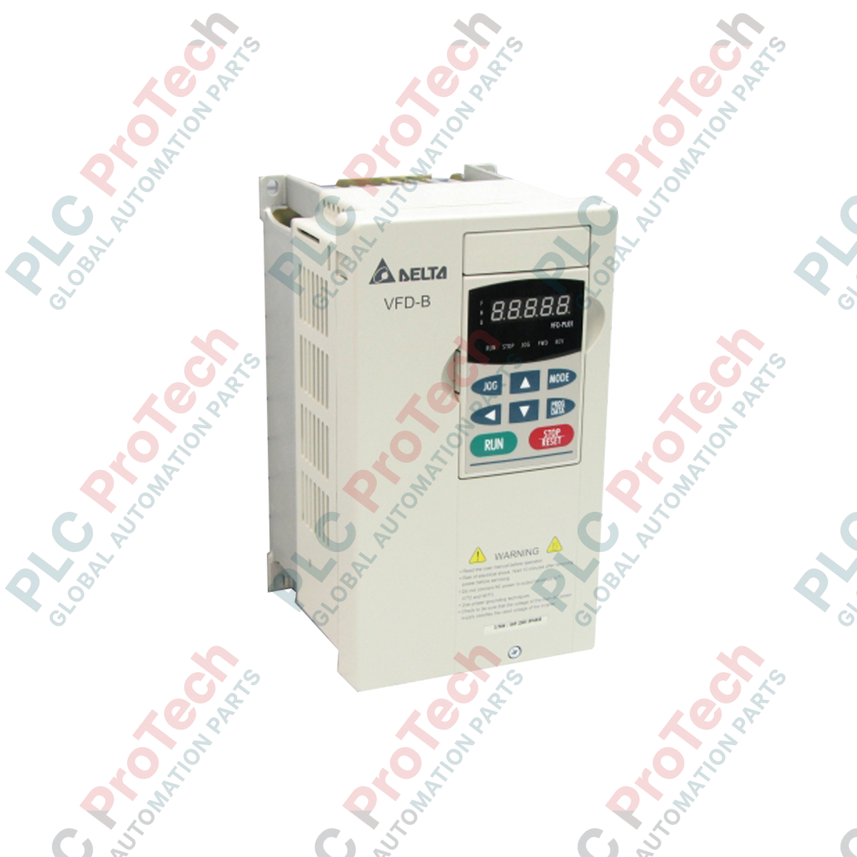
Le VFD022B21A (VFD022B21A) est un variateur de fréquence industriel polyvalent appartenant à la robuste série VFD-B de Delta. Ce variateur vectoriel AC sans capteur haute performance offre une capacité moteur applicable de 2,2 kW (3 CV) et fonctionne sur une alimentation monophasée 230 V.
Conçu pour une régulation précise du couple et de la vitesse dans divers secteurs de l'automatisation industrielle — y compris les broches d'outils machine, les métiers à tisser textiles, les convoyeurs de transport, les mélangeurs d'eaux usées et les ventilateurs de ventilation commerciale — le module offre un excellent couple à basse vitesse. En optimisant la puissance délivrée selon les conditions de charge du rotor en temps réel, le variateur maintient une stabilité mécanique absolue de l'arbre, supprime les pics de courant induits par la charge et réduit les pannes imprévues des équipements pour éliminer les temps d'arrêt de production.
Décomposition de la nomenclature du numéro de pièce
Le code alphanumérique unique du VFD022B21A détaille ses spécifications structurelles et sa génération matérielle :
-
VFD : Variateur de fréquence (contrôleur électronique de moteur AC).
-
022: Capacité moteur applicable indiquant une puissance de 2,2 kW (3 CV).
-
B : Identifiant de la série de produits représentant la plateforme polyvalente VFD-B.
-
21: Classe de tension et spécification de phase désignées pour les réseaux d'entrée monophasés 230 V.
-
A : Code de version de génération spécifiant la conception standard de production.
Spécifications techniques
| Paramètre |
Spécifications |
| Modèle |
VFD022B21A |
| Marque |
DELTA |
| Origine |
Taïwan |
| Architecture du variateur |
Variateur vectoriel AC sans capteur à usage général |
| Capacité moteur applicable |
2,2 kW (3 CV) |
| Tension d'entrée nominale |
230 V CA (monophasé) |
| Spectre de tension de sortie |
Triphasé proportionnel à la tension d'entrée |
| Résolution du réglage de fréquence |
0,01 Hz |
| Endurance en surcharge |
150 % du courant de sortie nominal pendant 1 minute |
| Contrôle de la fréquence de saut |
Trois zones indépendantes, plage réglable de 0,1 à 400 Hz |
| Seuil de prévention du blocage |
Réglable de 20 % à 250 % du courant nominal |
| Topologie de refroidissement |
Refroidissement par ventilateur à air forcé intégré |
| Poids net du châssis |
4,5 kg |
| Poids d'expédition |
6,0 kg (emballage logistique amortisseur de chocs inclus) |
| Limites de stockage / transport |
-20 à +60 °C |
| Humidité de l'air admissible |
Inférieur à 90 % HR, sans condensation |
FAQ produit
Comment les ingénieurs configurent-ils la fonction « Fréquence de saut » pour résoudre les problèmes de bruit mécanique ?
Le VFD022B21A offre trois zones de fréquence de saut indépendantes réglables entre 0,1 et 400 Hz. Lorsqu’une structure de machine possède une fréquence de résonance spécifique provoquant des vibrations extrêmes ou un bruit harmonique fort à certaines vitesses, l’ingénieur programme ces bandes exactes dans les paramètres du variateur. L’onduleur accélérera ou décélérera alors rapidement à travers ces zones ciblées sans fonctionner en continu à l’intérieur d’elles.
Ce variateur peut-il accepter une entrée monophasée 230 V et entraîner un moteur AC triphasé standard ?
Oui. Le VFD022B21A est conçu spécifiquement à cet effet. Il accepte une alimentation monophasée 230 V AC à ses bornes d’entrée, la redresse en une tension stable de bus DC, puis utilise des transistors bipolaires à grille isolée (IGBT) internes pour l’inverser en une sortie AC triphasée entièrement réglable afin de commander des moteurs asynchrones triphasés standards.
Quelle fonction le niveau de prévention du blocage assure-t-il lors d’une forte décélération ?
Le mécanisme réglable de prévention du blocage (de 20 % à 250 %) surveille en continu la tension du bus DC interne et le courant de sortie. Si le moteur décélère trop rapidement sous une charge à forte inertie, l’énergie régénérative peut provoquer un déclenchement par surtension. La prévention du blocage retarde automatiquement la décélération ou prolonge le temps de rampe descendante pour maintenir les paramètres opérationnels dans des limites sûres.
Mise en service sur site et normes d’intégration au tableau
-
Flux d’air forcé et espacement d’installation : Montez le variateur VFD-B verticalement sur une plaque métallique non peinte et mise à la terre à l’intérieur de l’armoire électrique. Assurez-vous que le ventilateur de refroidissement intégré reste libre de toute obstruction. Maintenez un espace minimum de 50 mm sur les deux côtés horizontaux et de 120 mm au-dessus et en dessous du boîtier du variateur pour maximiser la convection thermique passive et forcée.
-
Alimentation et interface moteur : Connectez l’alimentation monophasée 230 VAC entrante exclusivement aux bornes principales désignées (généralement L1/R et L2/S). Branchez les fils moteur triphasés directement aux bornes U, V et W. Ne branchez jamais les lignes d’alimentation AC entrantes aux bornes U, V ou W, car appliquer la tension de ligne brute à l’étage de sortie détruirait les transistors de commutation internes.
-
Routage des câbles de blindage et de commande : Faites passer toutes les lignes de sortie moteur haute tension à travers des conduits séparés et mis à la terre, éloignés des câbles de commande basse tension et des signaux analogiques (comme les potentiomètres de vitesse 0-10 V ou les boucles PLC 4-20 mA). Utilisez des câbles en cuivre blindés symétriques pour les connexions moteur, et mettez à la terre le blindage tressé à la fois à la base du châssis de l’entraînement et sur le cadre du moteur pour atténuer les interférences électromagnétiques (EMI) à haute fréquence.