Présentation des performances de contrôle de mouvement
Le Delta ASD-A2-1021-E (ASD-A2-1021-E) est un variateur servo AC numérique à large bande passante conçu dans la série phare ASDA-A2 de Delta, dédiée au contrôle de mouvement haute performance. Utilisé dans des industries automatisées exigeantes — telles que les machines d’étiquetage à grande vitesse, les systèmes d’inspection optique de précision, les lignes d’emballage multi-axes et les réseaux de traitement textile — ce variateur régule des moteurs synchrones à aimants permanents. En intégrant des algorithmes avancés de contrôle de boucle de position avec une synchronisation matérielle en temps réel, le variateur offre des réponses rapides de boucle, minimise le dépassement mécanique et protège les mécanismes à grande vitesse des erreurs de positionnement lors des transitions de charge soudaines.
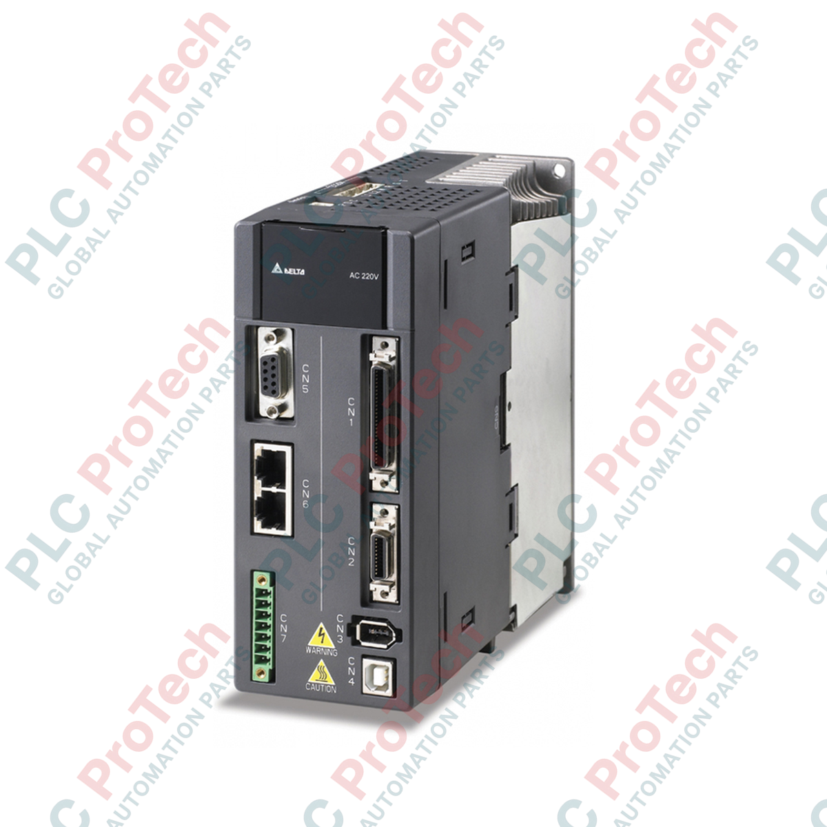
Topologie de contrôle et architecture de l’étage de puissance
Ce contrôleur de mouvement de 1 kW est conçu pour une intégration sur réseau monophasé 220 VAC, fonctionnant dans les tolérances de tension industrielle standard. Le variateur utilise une modulation de largeur d’impulsion vectorielle spatiale (SVPWM) avancée pour générer des formes d’onde de courant sinusoïdales et lisses aux enroulements du moteur, ce qui réduit considérablement les ondulations de couple et le chauffage du moteur. Fonctionnant en variante modèle « E », ce variateur intègre des capacités avancées de réseau fieldbus en plus de ses interfaces numériques impulsion/direction et analogiques standard. L’architecture du variateur comprend une interface de retour d’information haute densité 20 bits, un circuit de résistance de freinage régénératif intégré et des filtres automatiques avancés pour gérer la résonance mécanique.
Matrice des performances techniques
| Paramètre clé |
Spécification fonctionnelle |
| Numéro de modèle |
ASD-A2-1021-E |
| Marque / Famille de produits |
Delta Electronics / Série haute performance ASDA-A2 |
| Classification de la puissance du variateur |
1,0 kW |
| Tension d’alimentation entrante |
Monophasé 220 VAC |
| Méthode de commutation de contrôle |
Contrôle SVPWM (modulation de largeur d’impulsion vectorielle spatiale) |
| Résolution du système de retour d’information |
Traitement encodeur 20 bits (1 280 000 impulsions par révolution) |
| Classification du modèle d’interface |
Variante type E (interface fieldbus embarquée avancée) |
| Configurations de réglage |
Auto-réglage dynamique / réglage manuel avancé des paramètres |
| Atténuation de la résonance |
Filtres en encoche automatisés à double étage & lissage passe-bas |
| Dissipation régénérative |
Résistance de freinage régénérative interne intégrée |
| Protection contre les intrusions |
IP20 / Installation de type ouvert UL |
| Poids net du matériel |
2,0 kg |
| Poids brut à l’expédition |
4,0 kg (emballé dans un carton industriel robuste) |
Diagnostics industriels et FAQ
Comment effacer une erreur de communication d’encodeur (ALE011) au démarrage du système ?
Une faute ALE011 indique une défaillance du lien de données série entre l’interface encodeur du variateur et le moteur. Inspectez d’abord le câble de retour haute flexibilité pour détecter des brins internes cassés ou des conducteurs pincés. Assurez-vous que les broches du connecteur ne sont pas contaminées par des fluides de coupe ou de la poussière métallique. Enfin, vérifiez que la tresse de blindage du câble est bien fixée à la plaque de masse du variateur pour éviter que le bruit de commutation PWM haute fréquence ne corrompe le flux de données série 20 bits.
Quelle action entreprendre si la résistance régénérative interne surchauffe lors d’inversions cycliques ?
Lorsque des profils fréquents de démarrage-arrêt ou de descente sur axe vertical provoquent des surcharges thermiques régénératives (ALE05), la résistance intégrée ne peut pas dissiper en toute sécurité l’énergie cinétique renvoyée. Désactivez le circuit de résistance interne en retirant le cavalier installé en usine sur les bornes d’alimentation. Installez une résistance de freinage industrielle externe de capacité supérieure entre les bornes P et D, puis mettez à jour les paramètres de résistance et de puissance correspondants dans la banque de paramètres du variateur.
Le variateur ASD-A2-1021-E peut-il piloter un moteur 1,0 kW d’un autre fabricant ?
Bien que le variateur soit optimisé pour les moteurs synchrones à aimants permanents de la série ECMA de Delta, il peut piloter des moteurs tiers à condition qu’ils correspondent à la tension monophasée 220 V et aux puissances nominales. Cette configuration nécessite une saisie manuelle des paramètres du moteur cible (nombre de pôles, résistance d’enroulement, inductance) dans le variateur, suivie d’un auto-réglage statique ou en rotation complet pour calibrer les boucles de courant.
Directives de mise en service sur site et câblage
-
Conformité des bornes de potentiel principal : Connectez strictement les lignes d’alimentation monophasées 220 VAC entrantes aux bornes d’alimentation L1 et L2. Reliez les lignes servo de sortie aux bornes U, V et W. Ne connectez jamais les lignes d’alimentation entrantes aux bornes U, V ou W, car appliquer la tension secteur directement au bloc onduleur IGBT à semi-conducteurs entraînera une destruction thermique immédiate de l’étage de commutation.
-
Routage des câbles signal haute flexibilité : Séparez complètement la ligne de signal encodeur basse tension 20 bits des lignes moteur haute tension U, V, W et des câbles d’alimentation secteur. Maintenez une distance minimale de 200 mm dans des chemins de câbles ouverts ou utilisez des conduits métalliques indépendants et mis à la terre. Cela évite que le couplage inductif haute fréquence ne génère des tremblements de position ou des défauts de suivi dans la boucle de contrôle.
-
Dégagements thermiques et dissipation de chaleur : Montez le châssis IP20 verticalement sur un sous-panneau métallique plat et non peint pour maximiser la mise à la terre structurelle et le transfert thermique. Maintenez un périmètre dégagé d’au moins 50 mm de chaque côté et un dégagement vertical minimum de 120 mm au-dessus et en dessous du boîtier du variateur. Inspectez régulièrement l’unité pour garantir que les canaux de refroidissement internes restent exempts de fibres en suspension, de brouillard de graisse ou de débris conducteurs.