Présentation du système industriel
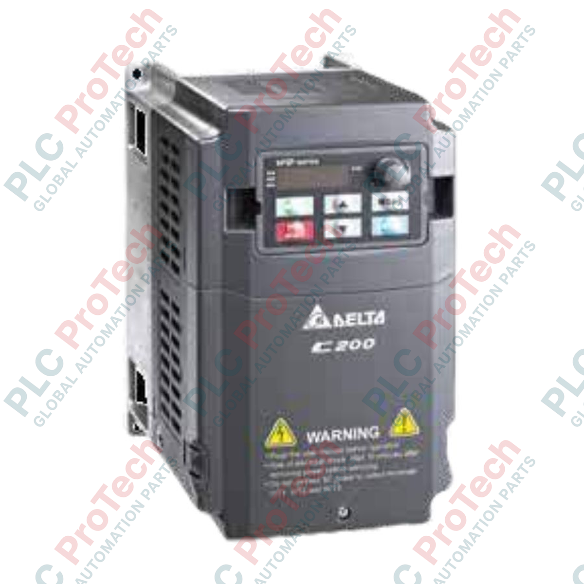
Le Delta VFD037CB23A-20 (VFD037CB23A-20) est un variateur de fréquence intelligent et économique conçu dans la famille Delta C200 de contrôle vectoriel intelligent. Déployé mondialement dans des processus d'automatisation commerciale et industrielle décentralisés — tels que les machines d'emballage lourdes, les enrouleurs textiles à grande vitesse, les machines de travail du bois et les configurations de convoyeurs multi-zones — ce variateur régule des moteurs asynchrones triphasés. En intégrant des algorithmes vectoriels haute performance dans un boîtier compact à montage mural, il assure une régulation stable de la vitesse, réduit les coûts d'exploitation et protège les composants de transmission sensibles contre les chocs de couple au démarrage.
Architecture électrique et dynamique du contrôle vectoriel
Ce convertisseur de fréquence à montage mural fonctionne sur une alimentation triphasée 230 V, avec un courant d'entrée nominal de 20 A pour fournir une puissance moteur applicable de 3,7 kW (5 HP). Il propose quatre modes de contrôle sélectionnables par logiciel : contrôle V/F standard, contrôle vectoriel sans capteur (SVC), contrôle V/F avec retour d’encodeur (VF+PG) et contrôle orienté champ avec retour d’encodeur (FOC+PG). Conçu avec des seuils opérationnels à double notation, le variateur atteint une fréquence de sortie maximale jusqu’à 600,00 Hz en mode Normal Duty, ou jusqu’à 300,00 Hz en mode Heavy Duty, avec une limite maximale de couple à 200 % du courant de couple.
Matrice de performance technique
| Paramètre principal |
Profil Normal Duty (ND) |
Profil Heavy Duty (HD) |
| Numéro de modèle |
VFD037CB23A-20 |
VFD037CB23A-20 |
| Marque / Série |
Delta Electronics / Série Smart Economy C200 |
Delta Electronics / Série Smart Economy C200 |
| Puissance moteur applicable |
3,7 kW (5 HP) |
3,7 kW (5 HP) optimisé pour un couple constant |
| Courant d'entrée nominal |
20 A |
20 A |
| Plage de fréquence de sortie |
0,00 à 600,00 Hz |
0,00 à 300,00 Hz |
| Méthodes de contrôle intégrées |
V/F, SVC, VF+PG, FOC+PG |
V/F, SVC, VF+PG, FOC+PG |
| Plafond de surcharge de couple |
-- |
Capacité maximale de courant de couple à 200 % |
| Tension d’alimentation |
Entrée AC triphasée 230 V |
Entrée AC triphasée 230 V |
| Mode d’installation mécanique |
Type A (format montage mural) |
Type A (format montage mural) |
| Indice de protection |
IP20 / UL Open Type |
IP20 / UL Open Type |
| Poids net de l’appareil |
1,5 kg |
1,5 kg |
| Poids brut à l’expédition |
3,0 kg (emballé dans un conditionnement anti-chocs) |
3,0 kg (emballé dans un conditionnement anti-chocs) |
Diagnostics industriels et FAQ
Comment déterminer s’il faut configurer le variateur C200 en mode SVC ou FOC+PG ?
Le contrôle vectoriel sans capteur (SVC) doit être choisi pour les applications haute performance standard où un encodeur ne peut pas être monté physiquement sur l’arbre moteur, car il calcule la position du rotor mathématiquement via des modèles électriques internes. Le contrôle orienté champ avec retour d’encodeur PG (FOC+PG) doit être utilisé pour les processus avancés nécessitant une régulation précise de la vitesse proche de zéro tr/min, un maintien absolu de position ou une réponse dynamique élevée du couple.
Quelle action doit être prise si le variateur déclenche une faute de surintensité (OC) lors des phases de démarrage brusques ?
Un déclenchement instantané OC à l’initialisation indique que le courant de sortie a dépassé le seuil de sécurité. Vérifiez d’abord que les données de plaque signalétique du moteur correspondent aux paramètres enregistrés dans le variateur. Ensuite, inspectez la ligne mécanique pour détecter tout blocage ou coincement, et évaluez le paramètre de limite de couple ; le VFD037CB23A-20 peut supporter jusqu’à 200 % du courant de couple, donc augmenter le temps d’accélération ou ajuster le décalage de la courbe V/F peut souvent stabiliser les cycles de démarrage à forte inertie.
Ce variateur nécessite-t-il un ventilateur de refroidissement externe pour les armoires fermées ?
Le variateur intègre un dissipateur thermique dimensionné pour évacuer la chaleur générée par l’étage de puissance de 3,7 kW. Cependant, comme il possède un indice IP20 de type ouvert, il doit être monté dans une armoire électrique ventilée. Assurez-vous que l’air circulant dans l’armoire est exempt de poussières métalliques conductrices et de brouillard d’humidité afin de protéger les bornes de puissance exposées.
Consignes de mise en service sur site et câblage
-
Connexions principales du réseau électrique : Raccordez les lignes d’alimentation triphasées 230 V uniquement aux bornes R/L1, S/L2 et T/L3. Connectez les câbles de sortie allant directement aux bornes moteur d’induction sur U/T1, V/T2 et W/T3. Ne jamais raccorder l’alimentation secteur brute aux bornes U, V ou W, car appliquer la tension directement au bloc de commutation de l’onduleur détruirait instantanément les transistors de sortie à semi-conducteurs internes.
-
Séparation de l’encodeur (carte PG) : En modes VF+PG ou FOC+PG, faites passer le câble de retour d’encodeur par des chemins de câblage séparés, éloignés des lignes moteur haute tension. Le câble d’encodeur doit utiliser des paires torsadées blindées avec la tresse globale reliée à la terre en un seul point proche de la masse du variateur. Cette séparation évite que les transitoires de commutation PWM ne perturbent le signal de retour et provoquent des erreurs de suivi de vitesse.
-
Disposition de montage et dégagement dans l’armoire : Installez le boîtier mural verticalement sur un sous-panneau métallique plat et non peint pour maximiser la conductivité de la mise à la terre. Maintenez un dégagement périphérique d’au moins 50 mm de chaque côté et un espace vertical minimum de 120 mm au-dessus et en dessous du variateur. Inspectez régulièrement l’appareil pour vous assurer que les ailettes de refroidissement restent dégagées de fibres en suspension ou de graisse, ce qui pourrait dégrader l’efficacité thermique.