Présentation du produit
Le EK1100-0008 (EK 1100-0008) est un coupleur EtherCAT spécialisé conçu pour les environnements industriels à forte vibration et à espace restreint où les connexions RJ45 traditionnelles peuvent être insuffisantes. Il sert de lien essentiel entre le réseau EtherCAT 100BASE-TX et les terminaux EtherCAT Beckhoff (série ELxxxx). En utilisant 2 interfaces M8 blindées à vis, le EK1100-0008 assure une connexion physique étanche aux gaz et résistante aux vibrations, ce qui en fait un choix idéal pour la robotique mobile, les lignes de production automobile et les systèmes de mouvement à haute dynamique. Le coupleur convertit les télégrammes passant d’Ethernet 100BASE-TX en représentation du signal interne E-bus, supportant jusqu’à 65 534 terminaux dans un seul segment tout en maintenant un délai interne minimal d’environ 1 microseconde.
Configuration technique
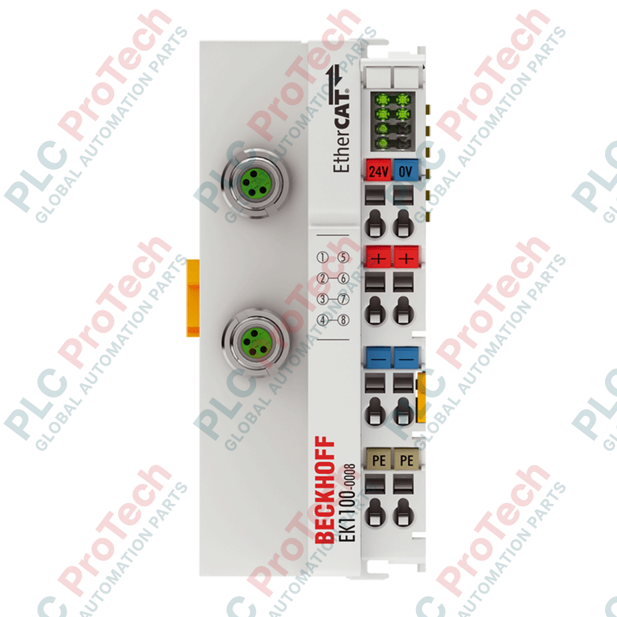
L’architecture du EK1100-0008 est conçue pour une distribution d’alimentation robuste et une intégrité du signal. Il dispose d’un système d’alimentation double : $U_S$ pour l’électronique interne et la communication E-bus (fournissant jusqu’à 2000 mA), et $U_P$ pour les contacts d’alimentation côté terrain (supportant jusqu’à 24 VDC / 10 A). Les interfaces bus M8 sont entièrement blindées et conformes au protocole EtherCAT 100 Mbit/s, supportant des distances allant jusqu’à 100 mètres entre stations. Le matériel comprend des LED de diagnostic intégrées pour le Link/Activity et l’état d’alimentation, logées dans un boîtier en polycarbonate de 44 mm. Avec une isolation électrique de 500 V entre les contacts d’alimentation, la tension d’alimentation et la couche Ethernet, il isole efficacement les perturbations du niveau terrain du réseau de contrôle.
Caractéristiques techniques
| Attribut |
Détails de la spécification |
| Modèle |
EK1100-0008 |
| Marque |
BECKHOFF |
| Origine |
Allemagne |
| Interface bus |
2 x M8 (Blindé, type vis) |
| Alimentation courant E-bus |
2000 mA |
| Débit de transfert de données |
100 Mbit/s |
| Contacts d’alimentation |
Max. 24 VDC / Max. 10 A |
| Alimentation électrique |
24 VDC (-15 % / +20 %) |
| Température de fonctionnement |
-25 à +60 °C |
| Dimensions (L x H x P) |
44 mm x 100 mm x 68 mm |
| Indice de protection |
IP20 |
| Homologations |
CE, UL, ATEX, IECEx |
| Poids |
150 g |
| Poids à l’expédition |
5,0 kg |
FAQ techniques
Quel est l’avantage principal des connecteurs M8 par rapport aux RJ45 dans les systèmes EtherCAT ?
La connexion à vis M8 sur le EK1100-0008 offre une stabilité mécanique supérieure et une meilleure résistance aux infiltrations environnementales comparée au RJ45. Elle est spécialement conçue pour éviter les déconnexions accidentelles ou les scintillements de signal dans les applications soumises à des mouvements constants ou à des vibrations à haute fréquence.
Comment est calculée la consommation de courant E-bus pour ce coupleur ?
La consommation de courant à partir de la tension de commande $U_S$ se calcule comme suit : $70\text{ mA} + (\sum\text{ courant E-bus} / 4)$. Si la demande totale en E-bus de vos terminaux ELxxxx connectés dépasse la capacité d’alimentation de 2000 mA du coupleur, un terminal d’alimentation supplémentaire (comme le EL9410) doit être intégré dans le segment.
Le EK1100-0008 supporte-t-il les zones dangereuses ATEX/IECEx ?
Oui, le module porte la marque Ex II 3 G Ex nA IIC T4 Gc, ce qui le rend adapté aux zones dangereuses de Zone 2. Pour ces installations, le coupleur doit être monté dans un boîtier répondant aux exigences de protection IP54 selon la norme.
Guide d’ingénierie et d’installation
Couple de serrage et blindage de l’interface M8 :
Lors de l’installation des câbles EtherCAT, les connecteurs M8 doivent être serrés au couple spécifié par le fabricant (généralement 0,4 Nm) pour garantir une étanchéité aux gaz et une continuité fiable du blindage. Utilisez uniquement des câbles blindés Cat.5 ou supérieurs avec connecteurs M8 4 broches codés D pour maintenir l’intégrité du signal 100BASE-TX sur la distance maximale de 100 m.
Câblage et distribution d’alimentation :
Le EK1100-0008 offre deux chemins d’alimentation 24 VDC séparés. Connectez l’alimentation $U_S$ (Système) aux broches 1 et 5, et l’alimentation $U_P$ (Périphérique/Terrain) aux broches 2 et 6. Utilisez les bornes à ressort pour le câblage ; les fils rigides ou multibrins de 0,08 à 2,5 mm² sont supportés. Assurez une longueur de dénudage de 8 à 9 mm pour garantir un contact correct. Si les appareils terrain tirent plus de 10 A, vous devez utiliser un nouveau terminal d’alimentation pour éviter d’endommager les contacts d’alimentation internes.
Position d’installation et gestion thermique :
Bien que la position d’installation soit variable, un montage horizontal sur un rail DIN de 35 mm est recommandé pour une dissipation thermique optimale. Assurez-vous que la connexion « double fente et clé » est correctement engagée avec le terminal adjacent pour maintenir l’intégrité des contacts de données E-bus. Dans les environnements atteignant la limite supérieure de 60 °C, maintenez au moins 30 mm de dégagement vertical pour une convection naturelle.