Présentation du produit
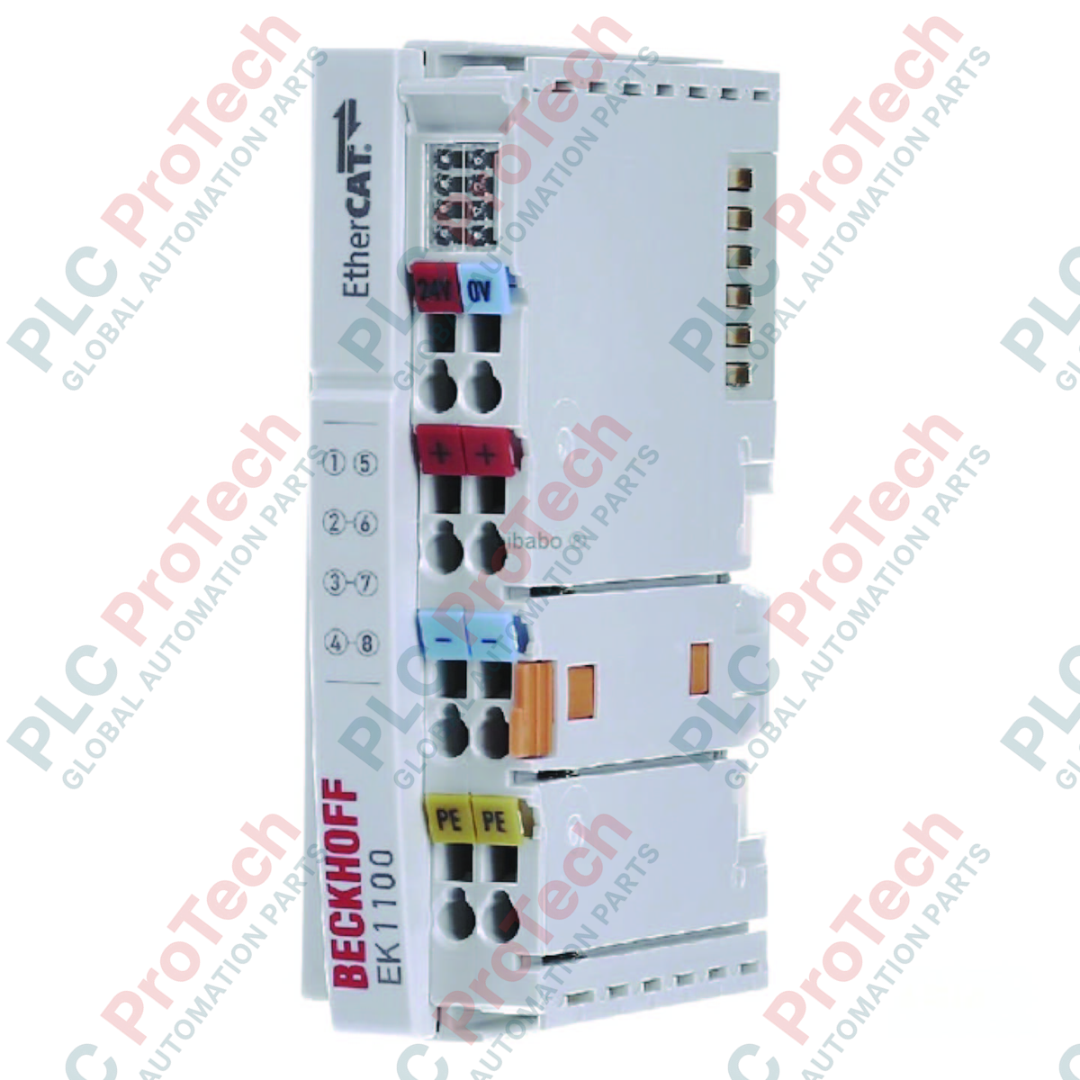
Le EK1100 (EK1100) est la pierre angulaire du système Beckhoff EtherCAT I/O, servant de lien haute performance entre les réseaux EtherCAT 100BASE-TX et les terminaux modulaires EtherCAT (série ELxxxx). Ce coupleur est conçu pour traduire les télégrammes basés sur Ethernet en signal interne E-bus à la vitesse du fil, assurant un transfert de données quasi instantané avec un délai d'environ 1 µs seulement. Supportant jusqu'à 65 534 terminaux individuels et disposant d'une alimentation robuste de 2000 mA pour l'E-bus, le EK1100 est destiné aux projets d'automatisation industrielle à grande échelle. Son boîtier en polycarbonate conçu en Allemagne est optimisé pour un montage sur rail DIN dans des environnements difficiles, offrant une isolation électrique de 500 V et des contacts d'alimentation intégrés pour simplifier la distribution du potentiel 24 VDC sur le bloc de terminaux.
Configuration technique
L'architecture du EK1100 met l'accent sur un débit élevé et un câblage simplifié sur le terrain. Il dispose de deux interfaces bus RJ45 : l'interface supérieure connecte le coupleur au réseau, tandis que l'interface inférieure peut être utilisée pour étendre le segment EtherCAT vers d'autres coupleurs ou succursales. L'alimentation intégrée fournit 2000 mA à l'E-bus, suffisante pour alimenter une forte densité de terminaux I/O. Le coupleur comprend également deux ensembles de contacts d'alimentation (jusqu'à 10 A) qui pontent automatiquement l'alimentation 24 VDC vers les terminaux suivants via les contacts à lame latéraux. Le câblage est facilité par un système à ressort résistant aux vibrations, supportant des sections jusqu'à 2,5 mm² (AWG 14), garantissant des connexions étanches aux gaz dans les machines à forte vibration.
Caractéristiques techniques
| Caractéristique |
Détails de la spécification |
| Modèle |
EK1100 |
| Marque |
BECKHOFF |
| Protocole |
EtherCAT |
| Interface bus |
2 x RJ45 (100 Mbit/s) |
| Distance max. entre stations |
100 m (100BASE-TX) |
| Alimentation courant E-bus |
2000 mA |
| Contacts d'alimentation |
Max. 24 V DC / 10 A |
| Alimentation |
24 V DC (-15 % / +20 %) |
| Température de fonctionnement |
-25 à +60 degrés Celsius |
| Indice de protection |
IP20 |
| Dimensions (L x H x P) |
44 mm x 100 mm x 68 mm |
| Poids |
env. 190 g |
FAQ techniques
Combien de terminaux EtherCAT puis-je connecter à un seul EK1100 ?
Le protocole EtherCAT supporte théoriquement jusqu'à 65 534 nœuds. Cependant, dans un seul bloc de terminaux, la limite pratique est généralement dictée par la consommation totale de courant de l'E-bus. Si vos terminaux dépassent les 2000 mA fournis par le EK1100, vous devez insérer un terminal d'alimentation E-bus (par exemple, EL9410).
Quelle est la fonction du second port RJ45 sur le coupleur ?
Le second port est utilisé pour le chaînage en série. Il permet au télégramme EtherCAT de « continuer » vers la station suivante (comme un autre EK1100 ou un répartiteur EK1122). Si aucun appareil n'est connecté au second port, le coupleur ferme en interne l'anneau pour renvoyer le télégramme au maître.
L’EK1100 nécessite-t-il une adresse IP spécifique ?
Non. Les dispositifs EtherCAT sont adressés en fonction de leur position physique dans le segment ou via un ID de dispositif explicite. Le EK1100 ne nécessite pas d'adresse IP pour un fonctionnement standard, ce qui simplifie la mise en service et évite les conflits d'adresses.
Guide d’ingénierie et d’installation
Calcul du courant E-bus :
Avant l'installation, additionnez les besoins en courant E-bus de tous les terminaux ELxxxx prévus pour le segment. Le EK1100 fournit un maximum de 2000 mA. Si la somme atteint 1800 mA, il est recommandé d’ajouter un terminal d’alimentation auxiliaire pour garantir la stabilité du système en conditions de forte charge et pour anticiper une éventuelle extension.
Câblage et blindage :
Utilisez toujours des câbles Ethernet blindés de catégorie 5 (Cat.5) ou supérieure. Les prises RJ45 sont blindées en interne ; assurez-vous que la tresse de blindage du câble fait un bon contact avec le boîtier du connecteur. Lors du câblage des contacts d’alimentation, utilisez des embouts pour fils multibrins afin que les bornes à ressort maintiennent une capacité de courant de 10 A sans échauffement localisé.
Installation et mise à la terre :
Montez le EK1100 sur un rail DIN de 35 mm conforme à la norme EN 60715. Le ressort de mise à la terre intégré à l’arrière du coupleur doit assurer un contact ferme avec le rail. Veillez à ce que le rail DIN soit connecté à la terre fonctionnelle (FE) de l’armoire de commande. Ceci est essentiel pour que l’isolation électrique de 500 V fonctionne correctement et pour protéger la communication Ethernet contre les interférences haute fréquence.