Application industrielle et valeur opérationnelle
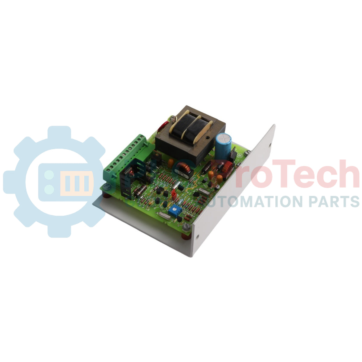
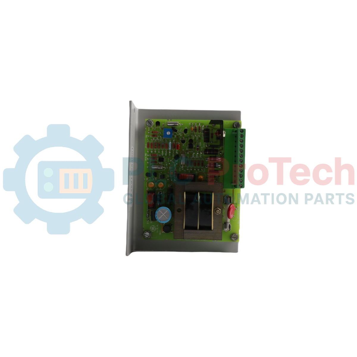
Le 531X207LCSAMG1 (531X207LCSAMG1) est une carte source de courant pour réseau local (LAN) renforcée, conçue par General Electric pour la conversion des variateurs et excitatrices de la série legacy 531X. Servant de nœud crucial de distribution d’énergie dans des armoires de variateurs complexes, ce circuit imprimé fournit des alimentations isolées et hautement régulées directement aux cartes de communication réseau critiques. Les industries lourdes telles que la sidérurgie, la production d’énergie et les centres d’exploitation minière comptent sur le 531X207LCSAMG1 (531X207LCSAMG1) pour maintenir des interfaces de données ininterrompues sur les nœuds de contrôle essentiels. Dans les architectures réseau multi-niveaux — telles que les architectures iFIX à double redondance ou les configurations SCADA dédiées au basculement gérant la synchronisation en temps réel des bases de données — cette carte évite les coupures réseau causées par des fluctuations locales d’alimentation. En assurant une alimentation fiable à la couche de communication, elle protège la surveillance des processus en temps réel, préserve la télémétrie système et minimise les arrêts de production coûteux et imprévus.
Architecture matérielle et contrôles de topologie
La conception fonctionnelle de la 531X207LCSAMG1 La carte d’interface alimentation et communication intègre un ajustement d’alimentation embarqué, un routage des signaux et des structures de mitigation des défauts.
-
Alimentation double rail : Convertit une entrée ligne 115 VAC protégée par fusible en sorties 5 VCC et 15 VCC hautement régulées, correspondant parfaitement aux besoins électriques de la carte LAN associée.
-
Calibration manuelle de sortie : Équipé d’un potentiomètre multi-tours embarqué permettant un réglage précis des niveaux de tension, ce qui permet aux techniciens sur le terrain de compenser les chutes d’impédance de ligne sur de longues courses internes du bus.
-
Interface de sélection configurable : Utilise un cavalier matériel robuste (désigné J1) qui permet aux ingénieurs de sélectionner explicitement les rails d’alimentation actifs pour s’adapter à des configurations de variateurs spécialisées.
-
Bornes de signal centralisées : Dispose d’un bornier robuste à 12 points en façade qui sert de jonction unique pour toute l’alimentation primaire entrante et les signaux de contrôle de communication sortants, simplifiant ainsi le dépannage.
Métriques et spécifications techniques
| Paramètre opérationnel |
Spécification technique |
| Identification du modèle |
531X207LCSAMG1 |
| Fabricant de la marque |
General Electric (cartes GE et contrôle turbine) |
| Séries de produits compatibles |
Série de remplacement 531X (variantes et excitatrices) |
| Classification du module |
Carte source de courant pour réseau local |
| Entrée d’alimentation principale |
115 VAC (monophasé, protégé par fusible) |
| Sorties secondaires régulées |
5 VCC et 15 VCC |
| Liens de sélection matérielle |
Bloc de cavalier J1 pour la configuration de sortie |
| Interface de calibration |
Potentiomètre de réglage de tension embarqué |
| Nœud de terminaison sur site |
Carte à bornes fixes à vis 12 points |
| Protection intégrée contre les surintensités |
Fusible d'alimentation intégré en façade |
| Limites de température ambiante |
0 à 60 °C |
| Dimensions physiques |
Profil standard GE 531X pour montage en rack |
| Masse du matériel |
0,38 kg |
| Pays d'origine |
États-Unis |
FAQ sur les performances de diagnostic
Comment le cavalier matériel J1 modifie-t-il la distribution d'alimentation du 531X207LCSAMG1 ?
Le cavalier J1 agit comme sélecteur matériel principal entre les rails d'alimentation 5 VDC et 15 VDC fournis à la carte de communication LAN associée. Le personnel de terrain doit positionner ce cavalier conformément aux exigences du manuel système du variateur ou du module émetteur-récepteur réseau spécifique connecté à la carte.
Quelle est la méthode correcte pour ajuster la sortie de tension en cas de chutes de ligne à l'intérieur de l'armoire de commande ?
Si les diagnostics au multimètre sur le bornier 12 points montrent de légères chutes de tension, les techniciens peuvent tourner le potentiomètre multi-tours intégré en face de la carte. Ce potentiomètre permet des ajustements fins des sorties DC mises à l'échelle, alignant les tensions d'alimentation aux tolérances nominales de 5 VDC ou 15 VDC.
Comment cette carte supporte-t-elle la synchronisation de la base de données SCADA lors de pannes réseau ?
La carte alimente le matériel sous-jacent qui maintient des chemins LAN redondants (LAN 1 et LAN 2) pour le réseau iFIX. En assurant une alimentation continue aux émetteurs-récepteurs, elle permet au système de basculer instantanément vers des chemins de communication secondaires ou tertiaires si la connexion au serveur SCADA principal échoue ou se déconnecte, préservant la synchronisation de la base de données sans perdre de données critiques du processus.
Protocole d'ingénierie de terrain et d'installation
-
Isolation de l'alimentation principale et protections par fusible :
Coupez et verrouillez la source d'alimentation principale 115 VAC avant d'insérer, de retirer ou de câbler le module. L'alimentation de ligne entrante est connectée directement via le bornier 12 points et représente un risque grave de choc électrique. Inspectez toujours l'état du fusible intégré embarqué avant la mise en service du système ; un fusible grillé indique une surcharge de courant ou un court-circuit interne sur les rails DC secondaires.
-
Couple de serrage des vis du bornier et dénudage des fils :
Dénudez tous les fils de terrain et d'alimentation destinés à la carte à bornes 12 points sur une longueur de 8 mm à 10 mm. Assurez-vous qu'aucune fibre de cuivre libre ne dépasse de la bouche du bornier. Serrez les vis du bornier avec un couple maximal de 0,5 N-m (4,4 inch-lbs). Des connexions lâches peuvent provoquer une accumulation locale de chaleur et du bruit électrique, ce qui peut interférer avec les bus de données LAN à haute vitesse à proximité.
-
Règles de calibration du potentiomètre :
N'utilisez que des tournevis d'ajustement isolés et non conducteurs lors du réglage du potentiomètre de calibration embarqué lorsque la carte est sous tension. L'utilisation d'un outil métallique standard risque de provoquer des courts-circuits accidentels contre les pistes de condensateurs sous tension à proximité, ce qui peut endommager les sous-circuits de régulation de tension et causer des dommages permanents aux émetteurs-récepteurs LAN connectés.