Présentation technique et déploiement industriel
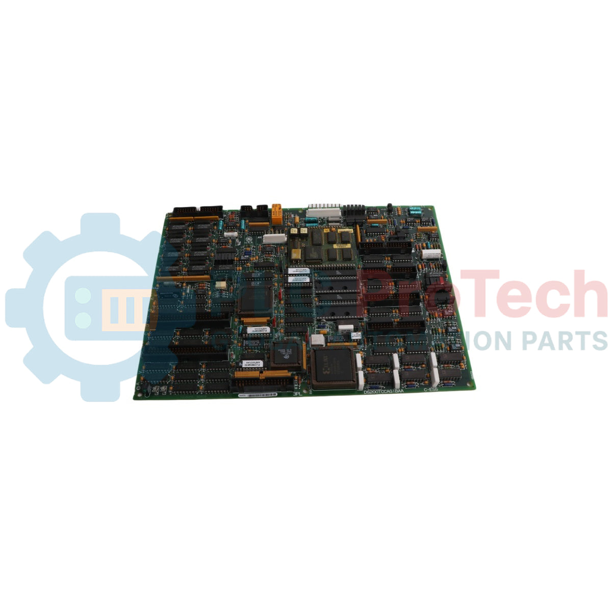
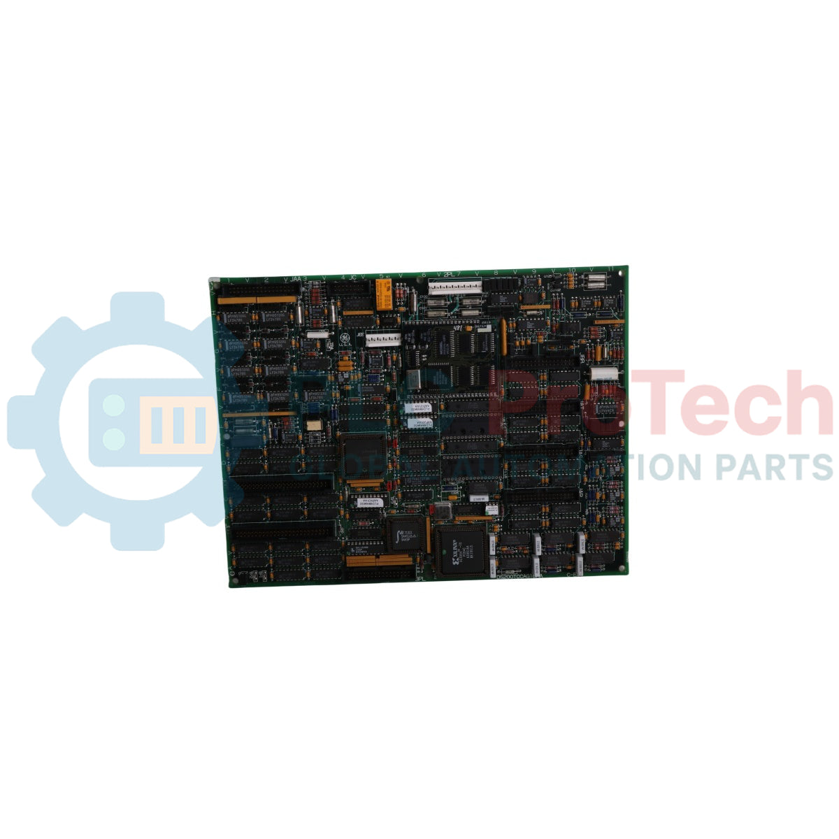
La DS200TCCAG1BAA (DS200TCCAG1BAA) est un instrument de traitement du signal analogique de niveau cœur développé par General Electric pour le cadre de contrôle des turbines à gaz et à vapeur Mark V Speedtronic. Fonctionnant depuis le cœur de contrôle central R5, cette carte d'interface multi-couches agit comme le nœud principal d'agrégation des données pour la télémétrie haute précision, mettant à l'échelle et conditionnant les entrées brutes du terrain avant de les transférer aux solveurs logiques du système. Les centrales électriques, les raffineries pétrochimiques et les usines de moteurs mécaniques lourds déploient la DS200TCCAG1BAA (DS200TCCAG1BAA) pour superviser les profils thermiques délicats, les boucles de courant multicanaux et les indicateurs de stabilité mécanique rotationnelle. En unifiant les signaux terrain multi-sources dans une structure de bus standardisée unique, la carte garantit un comportement prévisible du régulateur, protège les turbines lourdes en rotation contre les oscillations soudaines ou la fatigue thermique, et minimise les arrêts opérationnels imprévus dans les installations industrielles lourdes.
Circuiterie architecturale et cartographie des signaux
L'ingénierie structurelle de la carte DS200TCCAG1BAA intègre une logique microprocesseur discrète avec des sous-circuits d'acquisition multifonctionnels.
-
Logique microcontrôleur intégrée : Dispose d'un processeur Intel 80196 embarqué qui exécute des algorithmes indépendants de conditionnement du signal, mettant à l'échelle localement les données brutes du terrain à l'aide d'instructions stockées dans des blocs de mémoire programmable en lecture seule effaçable (PROM) enfichables.
-
Infrastructure de surveillance thermique : Intègre un circuit d'excitation RTD dédié et des calculs de compensation de jonction froide. Il surveille les variations de résistance RTD à travers les connecteurs JCC et JDD tout en traduisant les signaux thermocouples via l'interface de la carte terminale TBQA.
-
Gestion dynamique de la boucle de courant : Utilise des résistances de charge embarquées sur le chemin du connecteur JBB pour convertir les courants entrants des transducteurs 4-20 mA en paliers de tension lisibles, tout en fournissant simultanément des sorties de courant régulées 4-20 mA via le connecteur JAA pour alimenter des instruments distants.
-
Télémétrie de l'arbre de la turbine : Héberge des sous-systèmes spécialisés de surveillance de l'arbre qui suivent en continu le potentiel électrique et les fuites de courant à travers l'arbre de la turbine, fournissant une télémétrie vitale sur la dégradation de l'isolation au moteur central E/S via le bus 3PL.
Paramètres matériels et indices opérationnels
| Paramètre système |
Indice d'ingénierie d'usine |
| Désignation du modèle |
DS200TCCAG1BAA (carte mère : DS200TCCAG1) |
| Identifiant de marque |
General Electric (cartes GE & contrôle de turbine) |
| Série du système de contrôle |
Speedtronic Mark V (sous-série TC2000) |
| Acronyme fonctionnel |
Carte TCCA |
| Emplacement de montage du cœur |
Emplacement du châssis de contrôle R5 |
| CPU logique embarqué |
Microprocesseur Intel 80196 16 bits |
| Architecture de stockage du firmware |
Modules PROM enfichables et amovibles |
| Lien de communication maître principal |
Connecteur de bus de données 3PL (vers STCA / moteur E/S) |
| Alimentation des entrées analogiques sur le terrain |
Boucles 4-20 mA, thermocouples, RTD, moniteurs d'arbre |
| Dimensions physiques |
28.0 x 18.0 cm |
| Poids net du matériel |
0,45 kg |
| Protection du circuit imprimé |
Revêtement industriel normal |
| Hiérarchie des révisions matérielles |
Révisions fonctionnelles B et A, Révision du dessin A |
| Limites thermiques opérationnelles |
0 à 60 °C |
| Alimentation d'entrée logique |
Connecteur d'alimentation 2PL (alimenté via la carte TCPS) |
| Pays d'origine |
États-Unis |
FAQ sur le diagnostic technique
Quelles sont les fonctions principales des cavaliers matériels embarqués J1, JP2 et JP3 ?
Le cavalier J1 contrôle l'état opérationnel du port de programmation série local RS232. Le cavalier JP2 désactive l'oscillateur d'horloge intégré à bord, ce qui est nécessaire lors des routines de test et de benchmark au niveau de la carte. Le cavalier JP3 est un lien dédié aux tests en usine et doit rester à sa position d'usine par défaut pendant les opérations standard de la turbine.
Comment l'interface de l'espace de travail de l'opérateur est-elle physiquement reliée aux circuits de traitement de cette carte ?
L'interface opérateur (désignée comme ) est reliée à la carte DS200TCCAG1BAA via la carte terminale intermédiaire CTBA. La carte CTBA ancre les signaux 4-20 mA, se connectant à la carte TCCA via les connecteurs de sortie JAA et d'entrée JBB pour permettre un flux de données d'affichage fluide vers l'écran HMI.
Comment la carte TCCA concilie-t-elle différentes courbes de réponse thermique pour diverses configurations de thermocouples ou RTD ?
La carte repose sur des constantes de configuration d'E/S pilotées par logiciel plutôt que sur des réglages fixes des composants. Les ingénieurs terrain saisissent des coefficients spécifiques de capteurs et des types de courbes dans l'éditeur de configuration d'E/S sur le terminal HMI. Le microcontrôleur interne 80196 lit ces registres constants pour ajuster ses algorithmes de traitement pour chaque canal.
Protocole d'ingénierie et de maintenance sur site
-
Transfert du firmware PROM et précautions contre l'électricité statique :
Pour garantir la compatibilité logicielle lors du remplacement d'une carte, vous devez transférer les modules PROM originaux de la carte défectueuse vers l'unité de remplacement. Utilisez un tournevis à lame plate pour soulever uniformément chaque extrémité de puce de son socket, puis placez-la dans une pochette anti-statique. Le personnel doit porter un bracelet antistatique correctement mis à la terre tout au long de cette procédure pour éviter toute défaillance statique latente de la logique semi-conductrice.
-
Mise à la terre du blindage analogique et séparation des signaux :
Toutes les connexions analogiques passant par les connecteurs JAA, JBB, JCC et JDD doivent utiliser des conducteurs blindés à paires torsadées haute densité. Mettez à la terre les blindages en cuivre uniquement à la barre de terre désignée sur le tableau de bornes. Une mise à la terre flottante ou double crée des boucles de potentiel de terre, générant des ondulations électriques pouvant corrompre les mesures sensibles des thermocouples et des RTD.
-
Règles d'arrêt d'alimentation et restrictions liées au connecteur vestigial :
Isolez la prise d'alimentation 2PL avant d'insérer ou de retirer la carte TCCA du châssis central R5. Manipuler le module alors que le backplane est sous tension provoque des pics de tension sur le bus de données 3PL, risquant une corruption de la mémoire. De plus, le connecteur JEE est une disposition structurelle vestigiale ; ne branchez pas de câblage externe ni d'outils de débogage sur ce terminal pendant les opérations normales.