Vue d'ensemble au niveau système & valeur opérationnelle
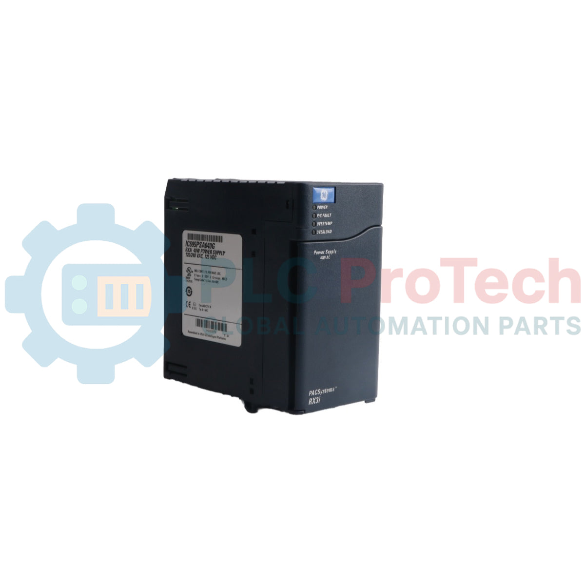
Le IC695PSA040 (IC695PSA040) est un module d'alimentation haute efficacité de 40 watts conçu pour la plateforme GE PACSystems RX3i. Fonctionnant avec des plages de tension d'entrée universelles de 85 à 264 VAC ou 100 à 300 VCC, ce module fournit une distribution d'énergie stable directement via le backplane pour alimenter les ressources locales de traitement et d'E/S. Les opérations industrielles dans les usines de traitement de l'eau automatisées, les installations de traitement chimique et les lignes d'assemblage manufacturières comptent sur le IC695PSA040 (IC695PSA040) pour garantir une exécution prévisible du contrôleur malgré les fluctuations de l'alimentation réseau. Le module d'alimentation isole l'électronique interne du rack des interférences électriques du terrain, enregistre les défauts prédictifs directement dans les tables du CPU lors de contraintes thermiques ou de charge, et maintient une capacité intégrée de maintien en cas de coupure. Cette résilience architecturale évite les arrêts soudains du PLC, protège les paramètres critiques d'exécution et réduit considérablement les temps d'arrêt imprévus coûteux.
Infrastructure architecturale & protection interne
La topologie matérielle du module IC695PSA040 est centrée sur la gestion localisée de la sortie à triple rail et la protection électronique automatique.
-
Sortie de tension à triple rail : Fournit indépendamment +5,1 VCC et +3,3 VCC pour répondre aux exigences des modules au niveau système RX3i, ainsi qu'une sortie relais dédiée de +24 VCC pour alimenter des modules relais de sortie externes.
-
Contrôles actifs de surintensité : Dispose d'une limitation électronique intégrée du courant qui plafonne le rail 5,1 VCC à 7 ampères et le rail 3,3 VCC à 10 ampères. En cas de surcharge ou de court-circuit, l'alimentation s'arrête automatiquement et lance des tentatives de redémarrage automatique continues jusqu'à ce que la faute sur le terrain soit résolue.
-
Diagnostic complet de l'état : Dispose d'une série de quatre voyants LED de premier plan couplés à des relais de diagnostic internes qui diffusent en temps réel la surchauffe, la surcharge et l'état des composants internes directement au journal des défauts du CPU central.
Données de performance & matrice matérielle
| Index d'ingénierie |
Spécification technique |
| Numéro de modèle |
IC695PSA040 |
| Identifiant de marque |
GE PACSystems (General Electric) |
| Série de système de contrôle |
Contrôleurs RX3i |
| Puissance de sortie totale nominale |
40 watts maximum au total |
| Tension nominale d'entrée |
120/240 VAC ou 125 VDC |
| Plage d'entrée AC |
85 à 264 VAC |
| Plage d'entrée DC |
100 à 300 VDC |
| Puissance d'entrée maximale |
70 watts maximum à pleine charge |
| Seuil de courant d'appel |
4 ampères pendant 250 millisecondes maximum |
| Spécifications de sortie de courant |
5,1 VDC (0 à 6 ampères), 3,3 VDC (0 à 9 ampères), 24 VDC (0 à 1,6 ampères) |
| Limites de tension |
5,1 VDC (5,0 à 5,2 VDC), 3,3 VDC (3,1 à 3,5 VDC), 24 VDC (19,2 à 28,8 VDC) |
| Isolation galvanique |
250 VAC continu (1500 VAC pendant 1 minute entrée vers backplane) |
| Durée de maintien |
Minimum 20 ms lors d'une interruption de source |
| Plage de câblage sur site |
Fil simple de 14 AWG à 22 AWG par borne |
| Capacité en chaîne en guirlande |
Jusqu'à 4 unités PSA040 |
| Limites de fonctionnement en air |
0 à 60 °C (température ambiante externe) |
| Code de protection ATEX |
II 3 G Ex nA IIC T3C |
| Pays d'origine |
États-Unis |
FAQ sur le diagnostic technique
L'alimentation IC695PSA040 peut-elle être configurée en parallèle pour obtenir une redondance N+1 ?
Non. Cette alimentation spécifique est conçue exclusivement pour une utilisation en solo dans un backplane universel RX3i (série catalogue IC695). Elle ne peut pas être associée à d'autres alimentations pour augmenter la capacité du système ou fournir une redondance matérielle. Tenter d'utiliser des versions plus anciennes (version IC695PSA040C et antérieures) avec une autre alimentation dans le même emplacement du backplane peut causer des dommages graves à l'équipement.
Qu'est-ce qui fait que le témoin LED principal d'alimentation passe du vert fixe à l'ambre ?
Une lumière verte indique que le module est sous tension et fournit avec succès des rails DC stables au backplane. Une lumière ambre montre que l'alimentation est correctement appliquée aux blocs de câblage d'entrée du module, mais que l'interrupteur à bascule du panneau avant est en position OFF, empêchant la livraison de puissance au rack.
Quelles défaillances systémiques sous-jacentes provoquent une coupure totale sans déclencher un indicateur de défaut LED externe ?
Un fusible interne non réparable se trouve dans la ligne d'entrée comme dernier recours matériel. Bien que le module active généralement une coupure électronique avant que ce fusible ne grille, un court-circuit interne extrême ou une surtension d'entrée excessive peut ouvrir ce lien de manière permanente. Lorsque ce fusible grille, toutes les indications de fonctionnement cessent et le module doit être remplacé physiquement.
Protocole d'ingénierie de terrain & maintenance
-
Atténuation des risques de choc électrique & sécurité de l'interrupteur marche/arrêt :
Pendant le fonctionnement actif avec une source d'alimentation AC, des tensions dangereuses (120 VAC ou 240 VAC) existent sur les structures internes du module. La porte d'accès aux borniers avant doit rester fermée pendant le fonctionnement normal pour éviter tout risque de choc mortel. Notez que l'interrupteur ON/OFF à bascule situé derrière la porte ne contrôle que les étages de sortie DC secondaires ; il ne déconnecte PAS l'alimentation secteur sous tension des borniers.
-
Insertion des fils et limites de couple :
Dénudez tous les conducteurs des borniers sur une longueur minimale de 9 mm à 11 mm. Assurez-vous que le fil est entièrement inséré dans le boîtier du bornier jusqu'à ce que l'isolation du conducteur soit en contact avec la butée d'isolation interne. Serrez les vis de serrage avec précaution, en veillant à ne pas dépasser le couple maximal admissible de 0,5 N-m (4,4 inch-lbs). Une insertion incorrecte peut provoquer un blocage de la vis sur l'isolation du fil, entraînant des circuits ouverts ou des points de terminaison chauds.
-
Cavalier de protection contre les surtensions & procédure de test Hi-Pot :
Les borniers inférieurs contiennent un circuit de surtension à varistance à oxyde métallique (MOV) qui doit être connecté à la terre du châssis à l'aide d'un cavalier installé par l'utilisateur pour une protection de base contre les surtensions d'entrée. Pour effectuer un test diélectrique haute tension (Hi-pot) sur l'alimentation, vous devez désactiver ce circuit de surtension en retirant ce cavalier. Réinstallez immédiatement le cavalier de terre après le test pour rétablir la protection contre les transitoires.