Présentation du produit
La DS215SLCCG1AZZ01A (DS215SLCCG1AZZ01A) est une carte d'orchestration réseau haute performance conçue pour les plateformes de contrôle de turbine Mark V de General Electric et les entraînements industriels lourds. Fonctionnant sous l'acronyme fonctionnel SLCC, cette carte de traitement local coordonne la télémétrie complexe du réseau local (LAN), offrant une interface intégrée pour les machines industrielles à grande échelle. Des infrastructures critiques — y compris les opérations de raffinage pétrolier, les centrales de production d'énergie à cycle combiné et les installations marines de compression massives — dépendent de la DS215SLCCG1AZZ01A (DS215SLCCG1AZZ01A) pour maintenir des boucles de communication ininterrompues entre le contrôleur principal de l'entraînement et les équipements de surveillance périphériques. Hébergeant des voies isolées et non isolées, le module gère les transitions synchrones des nœuds à travers des réseaux à double protocole. Cette stricte séparation des données atténue le bruit inductif sur les lignes, assure une synchronisation réseau de haute intégrité et prévient les pertes catastrophiques de communication qui entraînent des arrêts système non programmés et des temps d'arrêt des installations.
Sous-systèmes architecturaux et répartition des révisions
L'architecture du composant et le schéma d'identification de la DS215SLCCG1AZZ01A carte réseau déterminent sa capacité de communication et les limites d'intégration matérielle.
-
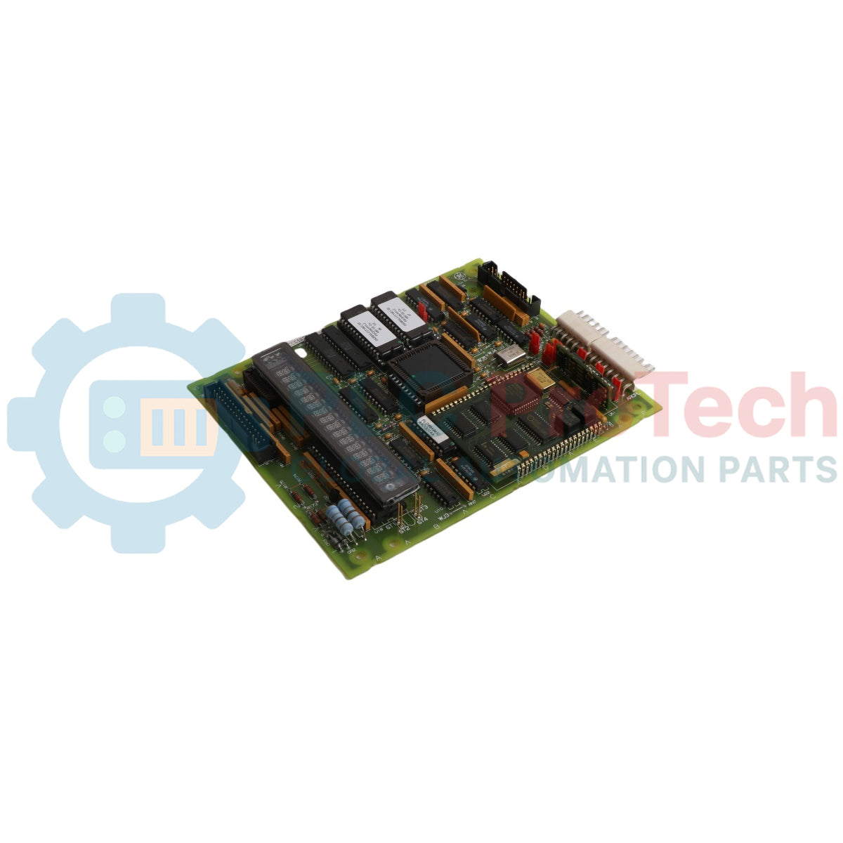
Moteur de contrôle à double protocole : Centrique autour d'un processeur de contrôle LAN intégré (LCP) désigné à la position U1. Ce nœud de traitement gère les transferts de données à haute vitesse sur les infrastructures réseau DLAN et ARCNET.
-
Allocation de mémoire enfichable : Utilise deux puces mémoire EPROM indépendantes et remplaçables sur le terrain, positionnées aux emplacements U6 et U7, pour héberger les fichiers du système d'exploitation LCP, associées à une RAM haute vitesse dédiée pour faciliter les échanges logiques en temps réel de l'entraînement.
-
En-têtes d'interface multipoints : Comprend cinq prises d'interconnexion haute densité distinctes : 2PL pour la distribution centralisée de l'alimentation, 3PL pour l'interface directe de la carte de contrôle de l'entraînement, 10PL pour les lignes de la carte terminale, ARCPL pour le routage spécialisé des signaux réseau, et KPPL pour les utilitaires d'interface du clavier portable.
-
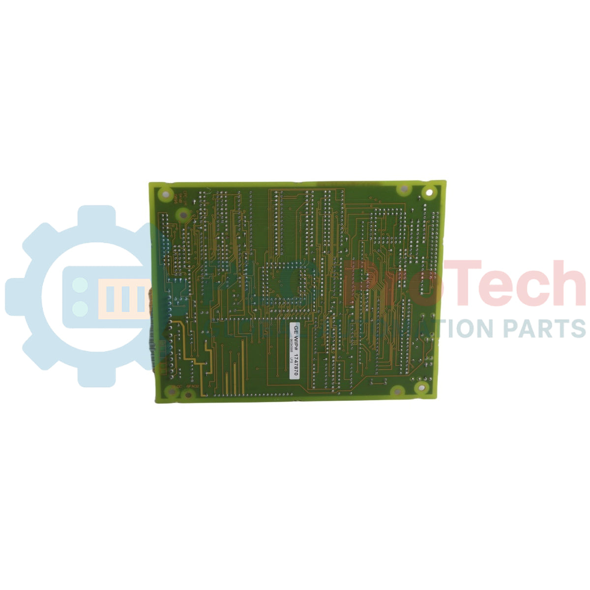
Décodage du suffixe fonctionnel : La chaîne alphanumérique finale définit les paramètres de construction de l'assemblage : famille de pièces fonctionnelles SLCC, code standard de revêtement conforme du circuit imprimé G1, révision matérielle de base A, niveau de mise à jour fonctionnelle d'ingénierie Z, indice de modification de la mise en page graphique Z, et identifiant de sous-classe de variation système 01A.
Spécifications techniques
| Indice système |
Métrique de performance structurelle |
| Identité du modèle |
DS215SLCCG1AZZ01A |
| Fabricant de la marque |
General Electric (GE) |
| Ligne de système de contrôle |
Systèmes Speedtronic Mark V / d'excitation de moteur |
| Classification du module |
Carte de communication réseau local (LAN) |
| Acronyme fonctionnel |
Groupe d'assemblage SLCC |
| Nœud de traitement principal |
Processeur de contrôle LAN dédié U1 (LCP) |
| Protocoles de données intégrés |
Réseau local distribué (DLAN) et ARCNET |
| Architecture de stockage du firmware |
EPROMs doubles remplaçables (emplacements U6 et U7) |
| Coque protectrice du circuit imprimé |
Revêtement conforme standard Classe G1 |
| Dimensions physiques |
18 cm L x 13 cm W x 3 cm H |
| Poids d'expédition du matériel |
0,65 kg (1 lb 7 oz) |
| Plage de fonctionnement environnementale |
Température ambiante de 0 à 50 °C |
| Origine de fabrication |
États-Unis (USA) |
FAQ sur l'intégration système et le diagnostic
Quelle fonction spécifique sur le terrain le cavalier JP19 remplit-il sur la carte circuit DS215SLCCG1AZZ01A ?
Le cavalier JP19 sert de lien matériel physique qui relie directement l'oscillateur à cristal de synchronisation embarqué au processeur principal de contrôle LAN. Modifier ce cavalier lors de la maintenance standard altère la synchronisation de l'horloge du microprocesseur et désactive immédiatement les communications réseau.
Comment les équipes sur le terrain peuvent-elles mettre à jour les fichiers du système d'exploitation de base hébergés sur une carte SLCC active ?
Les règles principales du logiciel de traitement sont intégrées dans des puces EPROM physiques à embase, positionnées aux emplacements U6 et U7. La mise à jour des paramètres du firmware ou le remplacement des partitions corrompues du système d'exploitation nécessite de substituer ces microprocesseurs physiques par des unités programmées en usine, plutôt que d'exécuter des utilitaires de téléchargement flash numérique via le bus de communication.
Quelle est la signification des circuits doubles isolés et non isolés intégrés sur la carte ?
La carte combine des circuits isolés pour les dérivations de ligne DLAN et ARCNET externes avec des circuits logiques non isolés pour la communication étroitement couplée avec le module de commande principal du moteur. Les chemins isolés utilisent des composants de protection galvanique pour garantir que les coups de foudre externes, les courts-circuits haute tension ou les transitions de champ électrique le long du réseau ne puissent pas pénétrer dans le bus central de l'ordinateur de commande du moteur.
Guide d'ingénierie et d'installation
-
Consignes de prévention contre les décharges électrostatiques :
Le DS215SLCCG1AZZ01A contient des processeurs CMOS haute densité et des chemins de registres volatiles très sensibles à l'électricité statique. Gardez la carte de remplacement scellée dans son sac conducteur protecteur jusqu'au moment juste avant l'insertion. Les techniciens doivent connecter un bracelet antistatique relié à la masse sur le rail structurel en acier non peint du panneau de l'enceinte avant de manipuler la carte, et tenir le module strictement par son bord extérieur en fibre de verre pour éviter tout contact cutané avec les pistes de soudure en surface.
-
Préservation des cavaliers matériels et limites de personnalisation :
Le module intègre des cavaliers manuels de type JP Berg ainsi que des cavaliers filaires d'usine (WJ) regroupés principalement dans le quadrant inférieur gauche du substrat PCB. La grande majorité de ces composants personnalisables sont réglés de manière fixe ou permanente en usine. Ne déplacez, ne contournez ni ne relocalisez aucun cavalier manuel par rapport à leurs positions documentées de base, car des configurations incorrectes corrompront les diagnostics système, déclencheront des incompatibilités de configuration matérielle ou entraîneront un échec d'initialisation du système.
-
Alignement et maintien des câbles d'interconnexion :
Lors de la connexion des nappes entre les ports 2PL, 3PL, 10PL, ARCPL et KPPL, inspectez les capots des connecteurs pour détecter les broches pliées avant l'engagement. Alignez correctement les clés pour éviter un appariement inversé des broches. Assurez-vous que les oreilles de verrouillage en plastique intégrées s'enclenchent complètement. Des prises de câble ruban lâches sous les vibrations continues du plateau de la machine créent une résistance de contact élevée, provoquant une dégradation intermittente du signal et des pertes de paquets réseau.