Présentation du produit
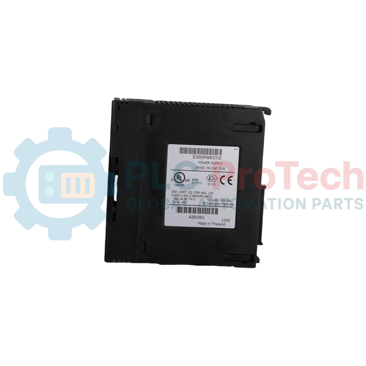
Le IC693PWR331E (IC693PWR331E) est un module de régulation d’alimentation DC haute capacité fabriqué par GE Fanuc pour la gamme de contrôleurs logiques programmables hérités Series 90-30 . Conçu pour fournir des rails électriques internes stables sur une plaque de base locale, cet appareil traite une entrée nominale large de 24 VCC pour délivrer trois potentiels électriques distincts avec une capacité de charge cumulée totale de 30 Watts. Les installations de processus continus lourds — telles que les usines de forge métallique, les usines de traitement des minéraux et les réseaux d’infrastructures d’eau décentralisés — comptent sur le IC693PWR331E (IC693PWR331E) pour maintenir la logique cruciale de traitement central et de communication E/S. En séparant la logique interne délicate de traitement +5 VCC des boucles d’instruments isolées +24 VCC et des commandes relais mécaniques +24 VCC, cette unité d’alimentation protège activement les processeurs système contre les retours inductifs de champ, assurant des opérations stables et réduisant significativement les arrêts forcés de l’usine.
Configuration technique et disposition du système
L’infrastructure interne, les chemins de gestion de l’alimentation et les interfaces de diagnostic de la carte d’alimentation centrale IC693PWR331E optimisent l’espace dans l’armoire et l’isolation des boucles.
-
Allocation de tension à triple rail : Distribue l’alimentation de manière dynamique sur trois sorties indépendantes, permettant jusqu’à 30 Watts absorbés par le bus critique +5 VCC tout en régulant une charge maximale de 15 Watts sur la ligne relais +24 VCC et une charge maximale de 20 Watts sur la ligne isolée +24 VCC, à condition que la charge nette totale ne dépasse pas 30 Watts.
-
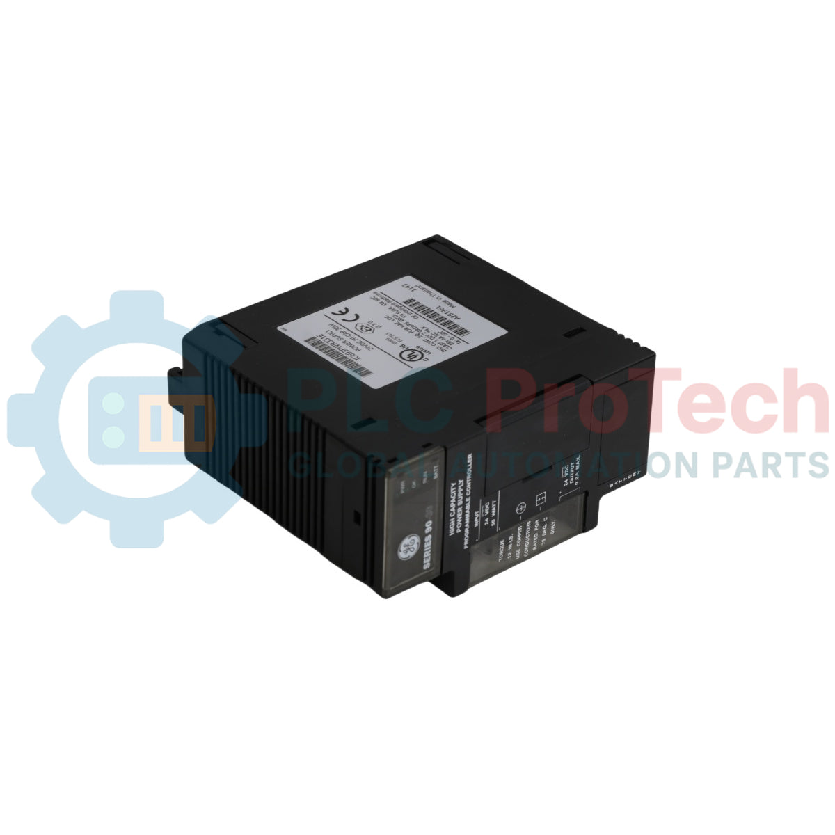
Interface réseau série embarquée : Dispose d’un lien de communication RS485 monté à l’avant, conçu pour fournir des connexions réseau directes aux programmateurs portables (HHP) ou aux postes de supervision exécutant des configurations logicielles GE Proficy.
-
Groupe de surveillance LED dynamique : Contient un bloc de statut dédié à quatre points (PWR, OK, RUN et BATT) qui affiche les états opérationnels instantanés, la synchronisation du CPU et les métriques de diagnostic de la batterie de secours interne.
-
Protection de la mémoire volatile : Contient une batterie de secours localisée derrière une porte battante protectrice avant, assurant l'intégrité des données des registres RAM volatiles du CPU du PLC lors des interruptions d'alimentation principales de la plaque de base.
Spécifications de performance et métriques principales
| Métrique de puissance |
Norme de spécification système certifiée |
| Identité du modèle |
IC693PWR331E |
| Fabricant de la marque |
GE Fanuc Emerson (Division Solutions d'automatisation) |
| Ligne de système de contrôle |
Automate programmable Série 90-30 |
| Classification du module |
Bloc d'alimentation DC haute capacité |
| Tension nominale d'entrée |
Pistes potentielles 24 VDC / 48 VDC |
| Plages de fonctionnement en courant continu |
Fenêtre de démarrage : 21 à 56 VDC / Plage de fonctionnement : 18 à 56 VDC |
| Consommation en charge complète |
Entrée active de 50 Watts / Limites alternatives de surtension de 90 VA |
| Surge d'appel de courant maximal |
Courant de crête de 4 A durant moins de 100 ms |
| Répartition de la sortie de tension |
5 VDC (30 Watts max) / Relais 24 VDC (15 Watts max) / Isolé 24 VDC (20 Watts max) |
| Capacité combinée totale |
Sortie maximale nette de 30 Watts |
| Intervalle de maintien de l'alimentation |
14 millisecondes de tampon de chute minimale sécurisée |
| Interface de communication |
Port de protocole série RS485 localisé |
| Indice de poids du matériel |
1,25 lb (0,57 kg) |
| Plage de fonctionnement ambiante |
Paramètres de température ambiante de la plaque de base de 0 à 60 °C |
| Certification de conformité |
Normes UL, CE approuvées |
FAQ sur l'architecture et le diagnostic de la plaque de base
Comment les ingénieurs gèrent-ils les ratios de distribution de puissance entre les trois boucles de sortie sur l'IC693PWR331E ?
Le module alloue la puissance de manière dynamique en fonction des besoins du backplane. Le rail critique +5 VDC peut tirer jusqu'à 30 Watts complets si les autres sorties ne sont pas utilisées. Cependant, lorsqu'il alimente des sorties discrètes en aval via la ligne relais +24 VDC de 15 Watts ou qu'il alimente des transmetteurs externes sur le bornier isolé +24 VDC de 20 Watts, vous devez calculer la charge totale pour garantir que la consommation combinée reste en dessous de la limite structurelle de 30 Watts.
À quoi sert l'indicateur LED BATT avant et comment doit-il être surveillé ?
The BATT LED monitors the structural charge state of the internal lithium battery pack housed behind the front swing door. A normal state keeps this indicator clear, showing the battery is maintaining the volatile RAM registers of the Series 90-30 CPU. If the BATT LED illuminates, it indicates the voltage has dropped below the safe threshold, and the battery must be replaced while the baseplate is powered up to prevent logic memory loss.
Can the IC693PWR331E handle temporary incoming DC power drops without causing a CPU fault?
Yes. The power supply module includes an internal filtering matrix that delivers a minimum holdup time of 14 milliseconds. This allows the system to ride through minor DC input voltage drops or local switching transients without triggering a power failure signal or causing the main processor to execute an emergency shutdown.
Engineering & Installation Guide
-
Baseplate Slot Insertion and Frame Grounding:
The IC693PWR331E must be installed in the leftmost slot of the Series 90-30 baseplate chassis. Align the top and bottom structural hooks of the module with the chassis cutouts and press the unit firmly until the lower locking lever snaps into place. Tighten the grounding terminal block screws to 0.5 N-m (4.4 inch-lbs) to ensure a solid electrical ground path to the enclosure frame, which helps dissipate high-frequency incoming line noise.
-
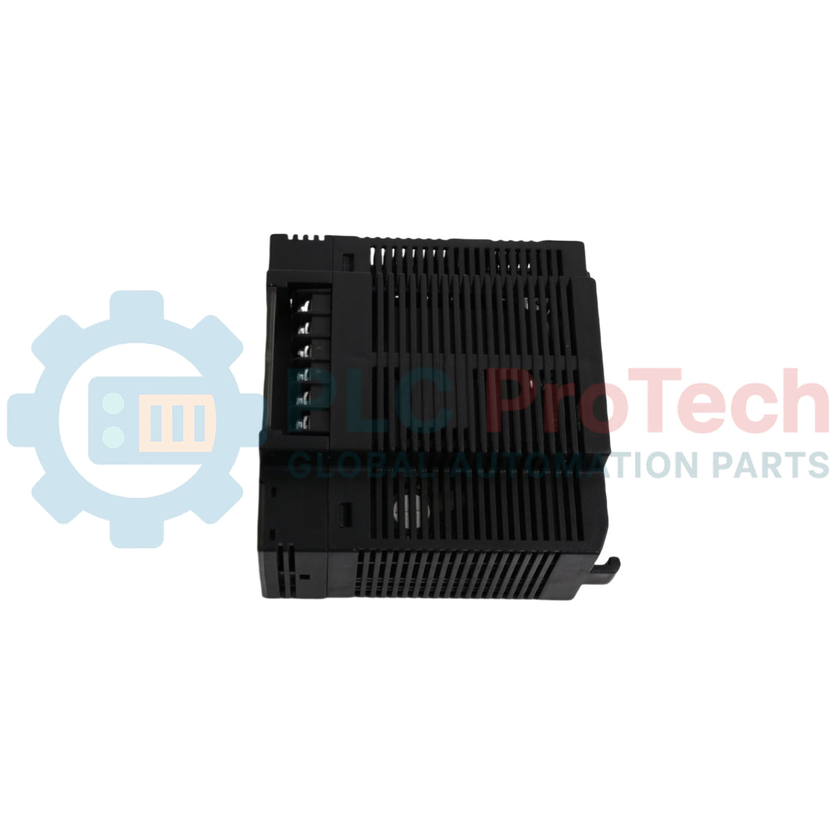
Isolated Terminal Connections and Instrument Sourcing:
The bottom screw terminal provides the isolated +24 VDC output, engineered to power external input circuits and internal analog loops. Run these isolated lines through independent, twisted control wires, keeping them separated from high-current AC cabling. This wiring method prevents inductive switching noise from crossing back through the power supply and distorting sensitive 12-bit analog conversions on adjacent cards.
-
Gestion environnementale et règles proactives d'espacement :
Parce que cette alimentation repose sur la convection naturelle de l'air, elle doit être tenue à l'écart de la poussière, de la saleté et de tous les dispositifs générant de la chaleur à l'intérieur de l'enceinte du panneau. Maintenez un espace libre minimal de 5 cm au-dessus et en dessous du boîtier du module. Vérifiez périodiquement que l'air ambiant de l'armoire reste dans la plage de fonctionnement certifiée de 0 à 60 °C afin d'éviter que la fatigue thermique ne réduise la durée de vie des condensateurs de filtrage internes.