Présentation du produit
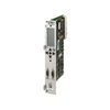
La IS200TTURH1B est une carte de terminaison de turbine spécialisée et à haute intégrité développée par GE Energy pour la série legacy du système de contrôle Mark VI Speedtronic. Fonctionnant comme interface câblée principale pour les systèmes électro-hydrauliques de turbines à vapeur et à gaz, cette carte reçoit directement les signaux terrain critiques nécessaires aux boucles de synchronisation et de protection contre la survitesse. Les installations industrielles à processus continu intensif — y compris les centrales thermiques industrielles, les réseaux utilitaires à cycle combiné et les grandes stations de compression de pipelines pétroliers et gaziers — s’appuient sur la IS200TTURH1B pour agréger des données télémétriques sensibles. La carte surveille les capteurs de vitesse magnétiques, ajuste les paramètres de synchronisation du générateur et commande les bobines des électrovannes hydrauliques de déclenchement. En fournissant des chemins de signal passifs robustes et un filtrage localisé des surtensions, cette carte garantit que le processeur principal reçoit des formes d’onde stables. Cette stabilité aide à prévenir les déclenchements dangereux de survitesse de la turbine et réduit les arrêts système non programmés.
Architecture du circuit et fonctions de traitement
La disposition spécialisée du circuit, les conditionneurs de signal localisés et les barrières terminales redondantes de la IS200TTURH1B maintiennent un contrôle strict en temps réel sur les paramètres critiques de fonctionnement de la turbine.
-
Canaux de capteurs de vitesse magnétiques : Équipés d’entrées passives dédiées pour capter des signaux d’impulsions passives haute fréquence provenant des capteurs de vitesse surveillant la rotation de l’arbre (RPM).
-
Isolation de synchronisation du générateur : Comprend des lignes d’interface avec transformateurs de tension intégrés pour surveiller la tension du bus, la tension de ligne du générateur et les angles de phase lors des routines de synchronisation automatique.
-
Chemins de commande des électrovannes de déclenchement : Connecte directement les boucles du système de déclenchement d’urgence (ETS) pour distribuer en toute sécurité les courants d’activation importants vers les vannes de décharge hydraulique.
-
Connexion d’interface système : Se connecte au rack du processeur de contrôle principal via des câbles ruban haute densité, acheminant des signaux analogiques et discrets propres vers le backplane du système.
Normes de performance technique
| Paramètre |
Norme de spécification certifiée |
| Identité du modèle |
IS200TTURH1B |
| Fabricant |
GE Energy (GE Vernova / Turbine Control) |
| Gamme du système de contrôle |
Série Mark VI Speedtronic |
| Classification du module |
TTUR - Carte de terminaison de turbine |
| Révision matérielle |
Variante fonctionnelle H1B |
| Gestion des entrées de signal |
Capteurs de vitesse, transformateurs de synchronisation, état des disjoncteurs |
| Actionneurs de sortie de signal |
Interverrouillages électrovannes hydrauliques de déclenchement, commandes de vannes |
| Protection par revêtement |
Couches de revêtement conformes de qualité industrielle |
| Configuration de montage |
Montage vertical sur panneau via rail DIN standard |
| Température de fonctionnement |
Plage environnementale continue de 0 à 60 °C |
| Température de stockage |
Contraintes de stockage sûres de -40 à +85 °C |
| Lieu de fabrication |
États-Unis (USA) |
Télémétrie turbine et FAQ de dépannage
Quels capteurs terrain spécifiques se connectent directement aux bornes de la carte IS200TTURH1B ?
La IS200TTURH1B accepte les entrées des capteurs de vitesse de turbine (tels que les capteurs à réluctance magnétique) et des transformateurs de potentiel (TP) qui surveillent la tension du bus et de la ligne du générateur. Elle reçoit également les lignes de retour d’état des disjoncteurs principaux du générateur et des interrupteurs auxiliaires de limite de déclenchement.
Comment le code de révision H1B impacte-t-il la compatibilité rétroactive lors des mises à niveau sur site ?
La désignation H1B identifie la disposition spécifique des composants matériels et le routage des pistes pour cette version de la carte TTUR. Lors du remplacement d’une carte défectueuse dans un panneau de contrôle Mark VI actif, les ingénieurs doivent correspondre à ce suffixe fonctionnel pour garantir que la carte s’adapte aux configurations de bornes existantes et interfère correctement avec le logiciel de contrôle.
Quels sont les signes courants d’une défaillance de traitement de signal sur cette carte de terminaison ?
Les défauts sur cette carte se manifestent généralement par des lectures de vitesse erratiques, des erreurs de synchronisation ou des alertes de diagnostic de circuit ouvert sur la station opérateur. Ces problèmes sont souvent causés par des connexions de fils lâches au bloc de bornes, une défaillance des filtres de surtension embarqués ou des câbles ruban endommagés menant au contrôleur central.
Guide d’ingénierie terrain et d’installation
-
Méthodes de mise à la terre des blindages pour les lignes de capteurs de vitesse :
Pour maintenir un suivi propre des impulsions sur les canaux de vitesse haute fréquence, faites passer tous les fils des capteurs terrain à travers des câbles d’instrumentation torsadés et blindés de haute qualité. Connectez le blindage extérieur du câble à la barre de terre dédiée du coffret uniquement côté carte de terminaison, et coupez proprement le blindage côté capteur. Cette pratique empêche les interférences électromagnétiques de perturber les flux d’impulsions et d’entraîner des lectures de vitesse erronées.
-
Manipulation antistatique pour la maintenance de la carte de contrôle :
Les composants de cette carte de terminaison sont sensibles aux décharges électrostatiques (ESD). Les ingénieurs terrain doivent porter un bracelet antistatique correctement relié au châssis de l’armoire avant de manipuler la carte ou de modifier des connexions de fils. Tenez le module strictement par ses bords en fibre de verre ou ses contours mécaniques pour éviter de toucher les pistes exposées.
-
Limites de couple des bornes et vérifications des connexions :
Fixez tous les fils terrain dans les blocs de bornes en respectant les valeurs de couple spécifiées par l’ingénierie afin d’éviter les connexions lâches. Des fils mal serrés peuvent provoquer une résistance de contact élevée, introduisant des erreurs de signal sur les boucles analogiques ou interrompant les circuits de déclenchement d’urgence à cause des vibrations basse fréquence du panneau.