Description
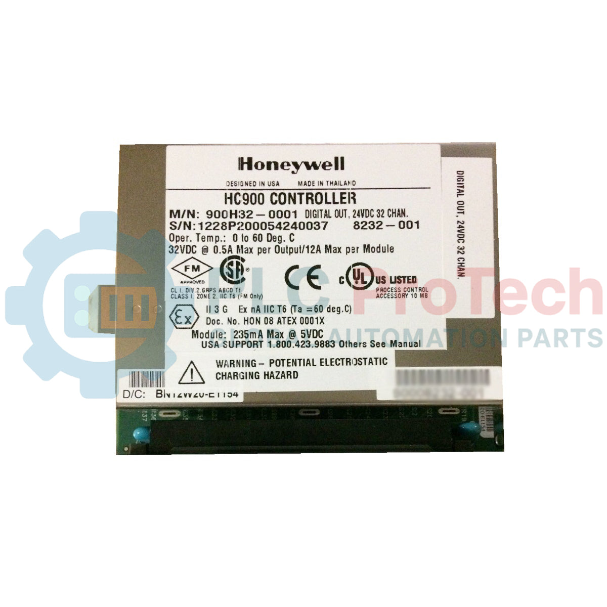
Designed to expand the output capacity of Honeywell HC900 controller architectures, the Honeywell 900H32-0001 serves as a high-density, high-reliability digital output interface. This module provides 32 current-sourcing, high-side outputs configured in isolated groups to interface seamlessly with field actuators, solenoids, relays, and indicator panels in demanding industrial environments.
To protect sensitive control electronics and maximize plant uptime, the module features galvanic isolation between internal logic and external field circuits. It also integrates intelligent current-limiting protection at the driver level, ensuring that transient overloads do not cause module failure or require physical power resets.
Features
-
32 High-Density Channels: Current sourcing, high-side driver configuration to maximize panel space efficiency.
-
Galvanic Isolation: Segmented into 2 isolated groups of 16 outputs each to minimize noise propagation and ground loops.
-
Active Overload Protection: Integrated electronic limiting arranged in 4 groups of 8 channels; self-resets without requiring module power cycling.
-
High Inrush Capability: Accommodates initial surge loads of up to 2 A for 10 ms, ideal for capacitive and inductive loads.
-
Status Diagnostics: Dedicated LED status indicators on the module faceplate for visual validation of channel states and fault diagnosis.
Applications
- Industrial Burner Management Systems (BMS)
- Multi-Zone Thermal and Environmental Control
- Water and Wastewater Treatment Plant Sequencing
- Critical Process Safety and Emergency Shutdown Interlocks
- Factory Automation Actuator and Valve Control
Technical Specifications
| Parameter |
Specification Value |
| Manufacturer |
Honeywell |
| Model Number |
900H32-0001 |
| System Compatibility |
HC900 Process Controller System |
| Output Count |
32 Outputs (Sourcing, High-Side Driver) |
| Galvanic Isolation |
2 Groups of 16 Outputs |
| Operating Voltage |
10.5 VDC to 32 VDC |
| Peak Voltage |
32 VDC |
| ON-State Voltage Drop |
0.15 VDC @ 0.5 A load |
| Overload Protection |
Active Current Limiting (4 groups of 8 channels) |
| Maximum Load Current |
0.5 A per point / 6.0 A max per group / 12.0 A max per module |
| Maximum Leakage Current |
0.15 mA @ 32 VDC |
| Maximum Inrush Current |
2.0 A for 10 ms |
| Response Time |
6 ms (OFF to ON / ON to OFF) |
| Shipping Weight (Calculated) |
3.0 kg |
Empirical Engineering Insights
Alternative Models & Compatibility
The 900H32-0001 is a direct drop-in replacement for high-density digital output configurations in the HC900 system. Note that older 16-point systems migrating to the 32-point module will require compatible 36-pin terminal blocks and appropriate wiring updates to access the additional channel banks.
Application Pitfalls & Engineering Notes
While each channel supports a nominal rating of 0.5 A, the aggregate module limit of 12.0 A must not be exceeded. If driving inductive loads such as heavy solenoids or magnetic clutches, verify that appropriate external suppression diodes are installed across the loads to prevent inductive flyback spikes from inducing premature wear on the module's high-side drivers.
Commissioning & Wiring Tips
Always structure the power distribution so that Group 1 (outputs 1-16) and Group 2 (outputs 17-32) are wired to appropriately fused external power sources. Ensure consistent grounding references between the external power supply and the module ground plane to mitigate potential electrical noise coupling across the galvanic isolation barrier.
Installation Guidelines
CRITICAL SAFETY WARNING
De-energize all primary, auxiliary, and field-side power sources before attempting hardware insertion, removal, or terminal terminal block manipulation. Failure to isolate power can result in transient arcs, module destruction, or severe electric shock.
1
Ensure the HC900 rack is mounted securely and completely powered down. Verify slot alignment keys match the module form factor.
2
Slide the module straight into the target chassis slot until the card edges seat firmly into the backplane connectors. Engage mechanical retention latches.
3
Terminate the external field and power supply wiring on the dedicated 36-pin terminal block assembly, ensuring clean wire stripping and proper torque specifications.
4
Connect the terminal block assembly to the module, secure the safety cover, apply field-side voltage first, and then power up the controller system backplane.