Présentation du produit
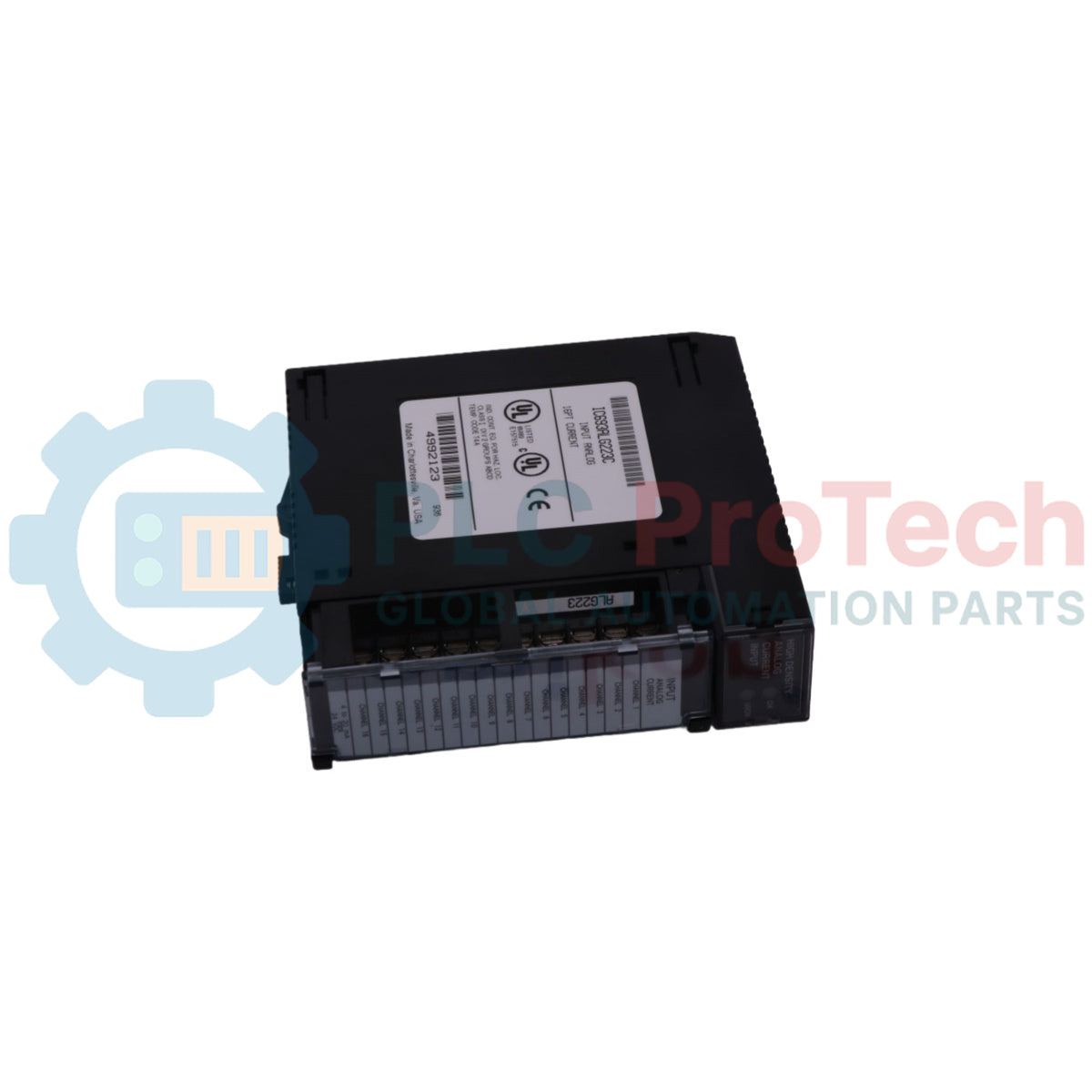
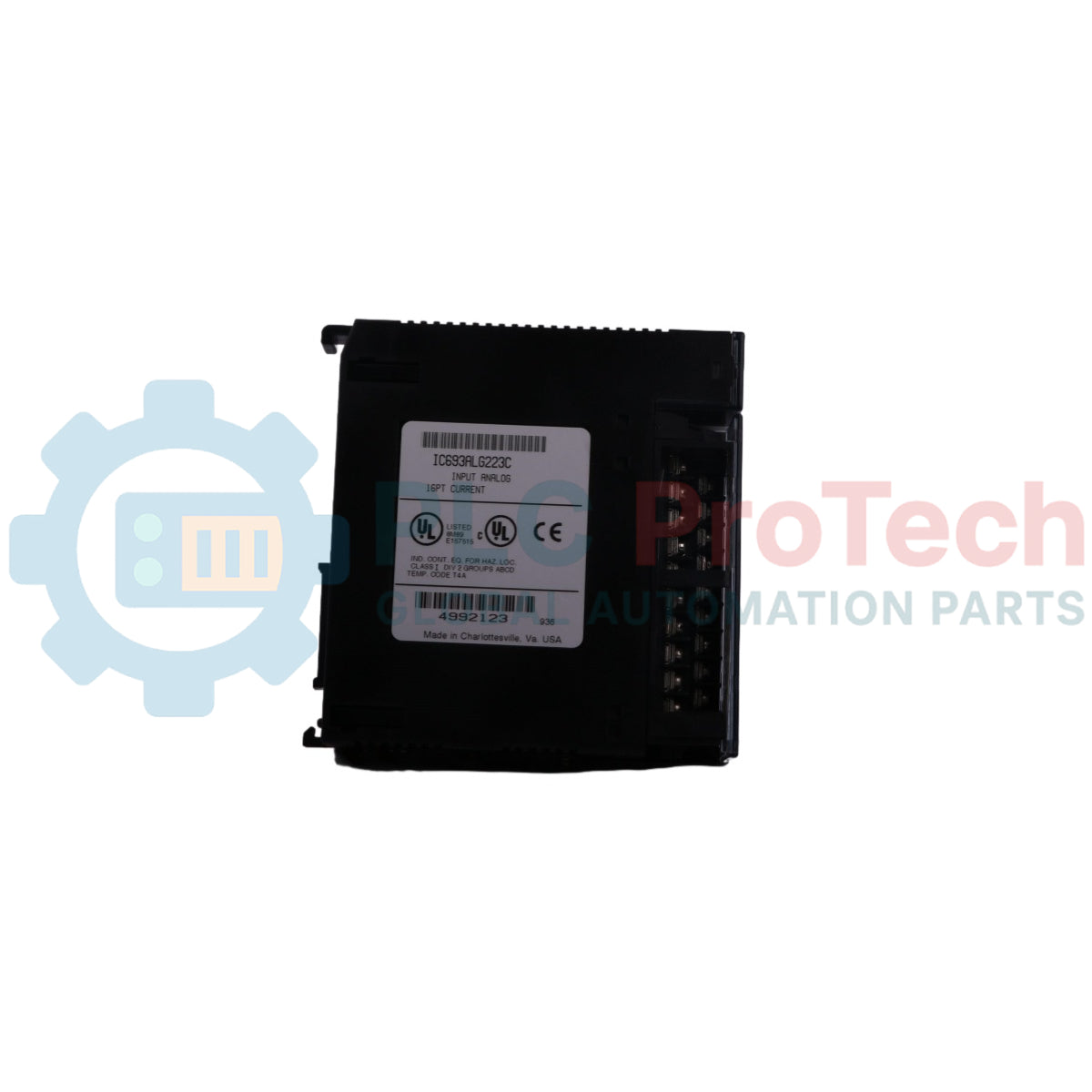
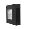
Le IC693ALG223 (IC693ALG223) est un module d’entrée courant analogique 16 canaux à haute densité et sécurité critique conçu par GE Fanuc pour l’infrastructure PLC héritée Series 90-30 . Conçu pour convertir les boucles de transmetteurs de terrain continues en comptes numériques nets et déterministes, cette unité matérielle offre jusqu’à 16 canaux d’entrée simple extrémité réglables sur trois plages de mesure indépendantes. Les environnements de traitement critiques — y compris les opérations de traitement de l’eau, les infrastructures de pâte et papier, et les usines locales de mélange chimique — s’appuient sur le IC693ALG223 (IC693ALG223) pour surveiller les variables physiques du système telles que la pression, le débit et les signaux de niveau. En intégrant une plage améliorée 4 à 20 mA, le module fournit activement une échelle numérique sous zéro jusqu’à 0 mA. Ce suivi spécialisé de boucle permet aux diagnostics logiciels de détecter immédiatement les défauts de fil ouvert, isolant les chutes d’instrumentation avant qu’elles ne corrompent les interverrouillages système et évitent des temps d’arrêt coûteux.
Architecture technique de configuration et de diagnostic
La topologie matérielle interne, les voies du signal d’entrée et la cartographie de l’allocation mémoire du module d’entrée courant IC693ALG223 définissent ses capacités de traitement.
-
Sélection flexible de plage par canal : Prend en charge la configuration autonome pour les profils 4 à 20 mA (0 à 32000 comptes), 0 à 20 mA (0 à 32000 comptes) et 4 à 20 mA amélioré (-8000 à +32000 comptes), sélectionnables par canal.
-
Détection de défaut de fil ouvert intégrée : La plage de courant améliorée utilise un décalage matériel spécialisé où les chutes à 0 mA correspondent à une valeur de -8000 comptes. Cela permet au processeur hôte de distinguer un déplacement valide de faible niveau du processus d’une rupture physique du fil de terrain.
-
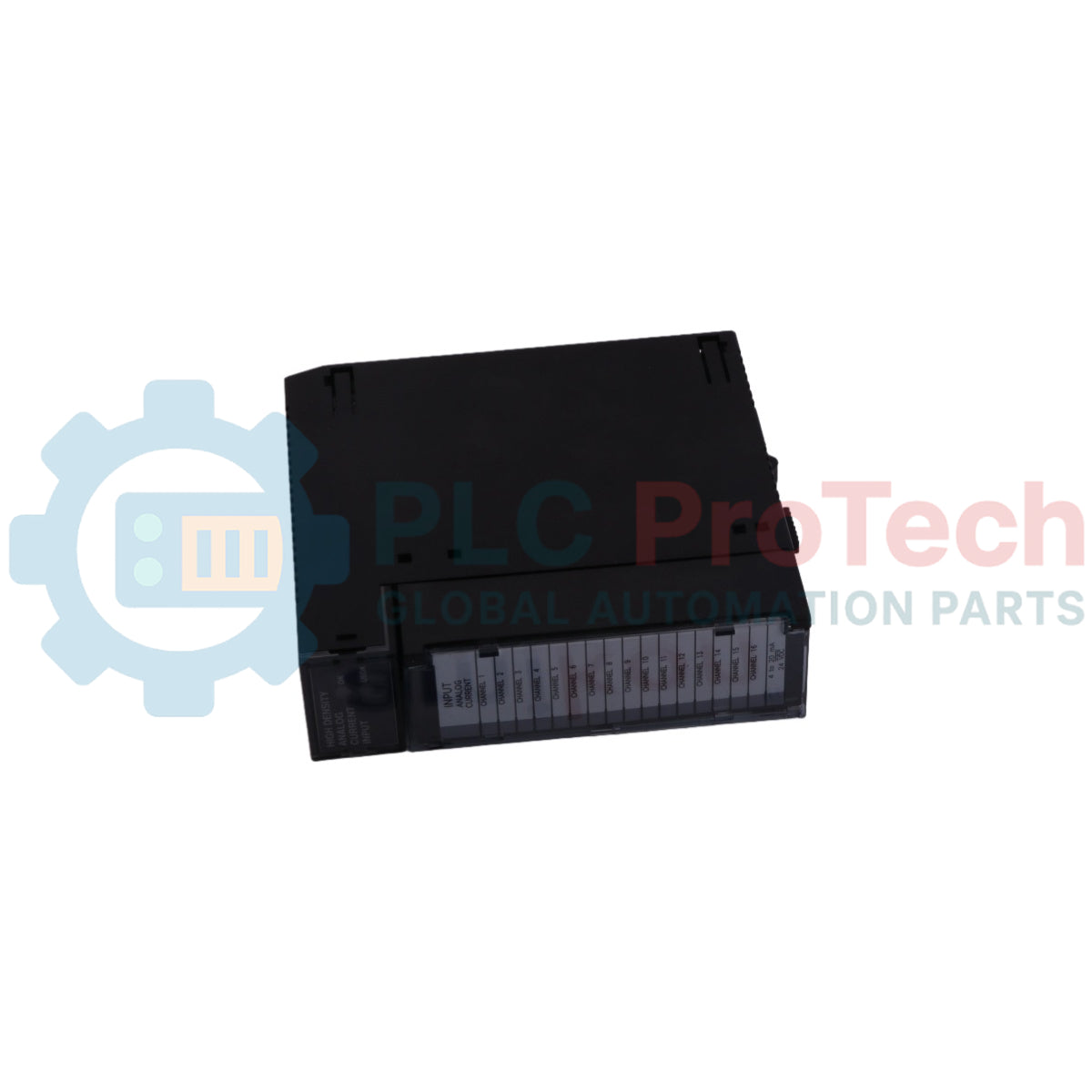
Surveillance fonctionnelle à double LED : Dispose de deux blocs d’état LED verts indépendants. La LED supérieure « MODULE OK » clignote en séquence pendant l’auto-diagnostic au démarrage, tandis que la LED inférieure « Alimentation utilisateur OK » vérifie en continu que l’alimentation externe en boucle analogique 24 VCC reste dans les paramètres opérationnels.
-
Mise à l’échelle dynamique de la mémoire de la baseplate : ajuste sa consommation de ressources E/S selon les paramètres du système, utilisant de 1 à 16 adresses de registre %AI pour les données de signal et de 8 à 40 bits %I pour transmettre en temps réel les états d’alarme haut/bas au CPU central.
Indicateurs de performance et spécifications principales
| Attribut matériel |
Spécification du manuel technique certifié |
| Désignation du modèle |
IC693ALG223 |
| Fabricant de la marque |
GE Fanuc (Série Automation) |
| Ligne de système de contrôle |
Automate programmable Series 90-30 |
| Classification du module |
Carte d’entrée de courant analogique simple-ended 16 canaux |
| Fenêtres de sélection d’entrée |
0 à 20 mA, 4 à 20 mA, 4 à 20 mA amélioré |
| Résolution analogique-numérique |
Capacité de résolution complète sur 12 bits |
| Échelle d’étalonnage par défaut |
4 µA par compte (4-20 mA), 5 µA par compte (0-20 mA / amélioré) |
| Taux de mise à jour du balayage des canaux |
13 millisecondes au total sur les 16 lignes actives |
| Précision absolue de la matrice |
+/- 0,25 % de l’échelle complète à 25 °C |
| Dérive thermique totale de précision |
+/- 0,5 % de l’échelle complète sur toute la plage opérationnelle |
| Isolation galvanique de tension |
1500 VCC en continu entre les bornes terrain et la partie logique |
| Niveau de rejet inter-canal |
Plus de 80 dB de 0 Hz à 1 kHz |
| Consommation électrique interne |
120 mA depuis le bus backplane 5 VCC / 65 mA depuis une source externe 24 VCC |
| Limites ambiantes de fonctionnement |
Paramètres opérationnels ambiants de 0 à 60 °C |
FAQ sur le fonctionnement matériel et l’allocation de la baseplate
Comment les ingénieurs identifient-ils les erreurs internes à l’aide des motifs de clignotement de la LED du module supérieur ?
L’indicateur « MODULE OK » affiche des codes de diagnostic clairs. Un état allumé fixe signifie que le matériel interne est vérifié et que la configuration du CPU est pleinement active. Un clignotement rapide continu indique que le module attend son fichier de configuration du CPU Series 90-30. Si la LED effectue une courte série de clignotements lents puis s’éteint complètement, le module a échoué aux diagnostics de mise sous tension ou a rencontré une erreur d’exécution de code irrécupérable.
Quels paramètres limitent le nombre total de cartes IC693ALG223 pouvant être installées dans un seul rack ?
La configuration du système repose sur deux facteurs principaux : les adresses de référence mémoire disponibles (%AI et %I) et la capacité de courant du backplane. Bien qu’un CPU Model 351 haut de gamme offre suffisamment d’espace d’adresses de référence pour supporter jusqu’à 51 modules, les ingénieurs doivent vérifier que la consommation totale de 120 mA par module sur le bus 5 VCC ne dépasse pas la capacité maximale en courant de l’alimentation de la baseplate installée.
Comment la plage améliorée détecte-t-elle un fil cassé par rapport aux configurations standard 4 à 20 mA ?
Dans les boucles standard 4 à 20 mA, un fil cassé fait chuter le courant d’entrée à 0 mA, ce qui s’arrête à une valeur de comptage 0 et peut masquer une boucle ouverte comme une variable de processus basse. La plage améliorée s’étend jusqu’à 0 mA comme -8000 comptes. Le logiciel système peut définir une limite d’alarme basse à environ -2000 comptes (3 mA) pour signaler instantanément une défaillance de boucle et déclencher des arrêts sécurisés par interverrouillage.
Protocole d’ingénierie et d’installation sur site
-
Raccordements de mise à la terre du blindage et réduction du bruit :
Pour maintenir une haute intégrité du signal en présence d’interférences RF sévères, tous les câbles de boucle analogiques doivent utiliser des fils blindés en paire torsadée. Raccordez les fils de drainage de blindage de l’instrument directement aux plots de mise à la terre optionnels désignés situés sur l’ensemble du bloc de bornes Série 90-30. Ne laissez pas les tresses de blindage brutes toucher les vis de signal adjacentes et maintenez une mise à la terre à point unique sur le boîtier du panneau pour éviter que des boucles de masse ne corrompent le suivi de conversion 12 bits.
-
Alimentation externe 24 VDC et points communs :
Le module nécessite une source d’alimentation externe +24 VDC fournie par l’utilisateur, câblée au terminal 18 pour alimenter l’électronique côté analogique. La ligne de retour négative de cette alimentation doit être reliée directement au terminal commun utilisateur sur le bloc. Assurez-vous que cette ligne d’alimentation reste propre, stable et sous un seuil maximal de ondulation de tension de 10 %, afin d’éviter que des bruits électriques externes ne provoquent des fluctuations de mesure sur les canaux d’entrée à simple extrémité.
-
Entretien du bloc de bornes amovible et alignement de montage :
Le module utilise un ensemble de bornes amovible pour permettre un pré-câblage et un remplacement rapide sur le terrain sans déconnecter les câbles de boucle. Lors du repositionnement du bloc de bornes sur le boîtier en plastique, alignez les crochets de retenue intégrés et serrez la vis de fixation centrale à 0,5 N-m (4,4 lb-pouce). Assurez-vous que toutes les vis des bornes sont serrées uniformément pour éviter des contacts à haute résistance sous les vibrations continues à basse fréquence des machines industrielles.