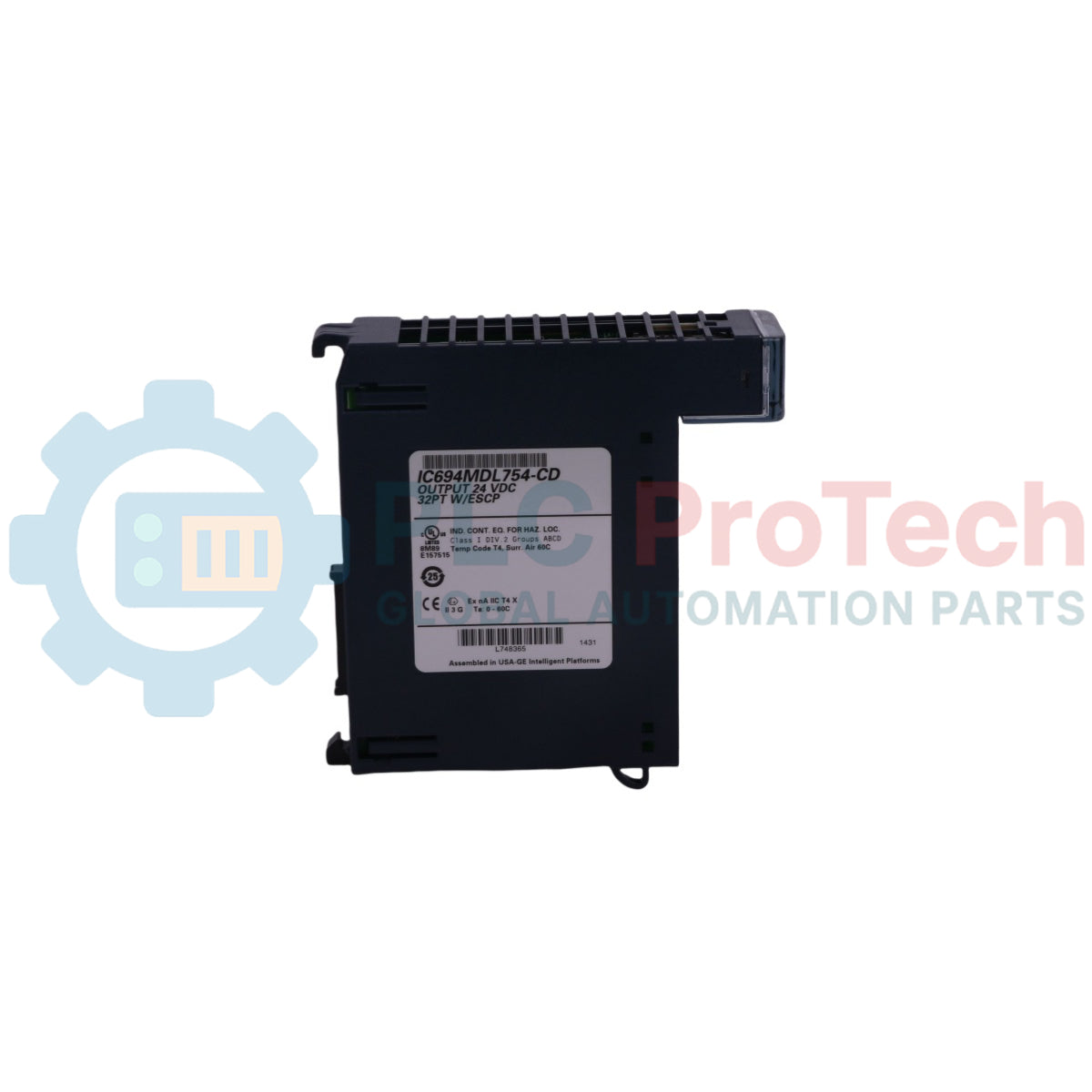
Présentation du produit
Le IC694MDL754 c’est un module de réponse à semi-conducteurs intelligent et haute densité conçu nativement pour la plateforme GE Fanuc PACSystems RX3i.. Fonctionnant comme un module de sortie logique positive 12/24 VCC Cette carte distribue localement l’alimentation à travers 32 points de sortie discrets pour exécuter des actions en temps réel.Les systèmes d’automatisation lourds — y compris les réseaux de distribution électrique, les lignes de traitement automatisées et les complexes de mélange chimique — s’appuient sur le IC694MDL754 pour orchestrer les composants matériels en aval tels que les électrovannes, les contacteurs externes et les lampes indicatrices. En séparant les 32 points discrets en deux groupes totalement isolés de 16 canaux, le module permet aux ingénieurs d’installer des niveaux de tension mixtes sur un seul châssis.. Sa protection intégrée contre les courts-circuits électroniques (ESCP) et ses diagnostics de surtempérature surveillent activement la santé des circuits, détectant automatiquement les courts-circuits graves à la terre et isolant les anomalies de terrain pour éviter des arrêts prolongés de l’usine..
Disposition architecturale et attributs diagnostiques
Le cadre matériel et les opérations de diagnostic du module de sortie logique IC694MDL754 assurent une coordination stable des composants à travers des réseaux de terrain très dynamiques.
-
Architecture d’alimentation à double groupe : Divise les 32 canaux de sortie en deux blocs électriques séparés de 16 voies.. Chaque groupe maintient une ligne commune indépendante, permettant au Groupe 1 de commuter des charges 12 VCC tandis que le Groupe 2 gère simultanément des charges 24 VCC jusqu’à une intensité maximale de 0,75 ampère par canal..
-
Circuiterie ESCP auto-récupérante : Dispose d’une protection électronique active contre les surintensités, les surcharges thermiques et les courts-circuits sur chaque point individuel.. Une fois la défaillance physique sous-jacente de la ligne ou la surcharge thermique éliminée, le pilote réinitialise automatiquement la sortie à son état opérationnel actif sans nécessiter de réinitialisation complète du CPU..
-
Matrice par défaut des sorties matérielles : Intègre un ensemble de doubles interrupteurs DIP embarqués sur le boîtier arrière, utilisés pour gérer les opérations de repli du système.. Les techniciens peuvent configurer le module pour forcer l'arrêt ou maintenir le dernier état en cas de défaillance des communications localisées..
-
Cartographie diagnostique complète : Transmet des codes d'état clairs à l'unité centrale RX3i, signalant les défauts individuels de points, les alarmes de perte d'alimentation côté terrain externe, le suivi de la présence des blocs de bornes mécaniques et les journaux de non-concordance de configuration des interrupteurs DIP.
Données de performance et spécifications techniques
| Métrique d'ingénierie |
Spécification du document d'usine |
| Désignation du modèle |
IC694MDL754 |
| Fabricant de la marque |
GE Fanuc (série PACSystems RX3i) |
| Classification du module |
Module de sortie, 12/24 VDC, 0,75 A, groupe de 32 points, avec ESCP
|
| Type de logique de sortie |
Type d'alimentation / logique positive (commute le côté positif de la charge)
|
| Plage de tension de sortie |
10,2 à 30 VDC
|
| Capacité totale de points |
32 sorties (deux groupes isolés de 16 canaux chacun)
|
| Courant de sortie maximal |
0,75 ampère maximum par point
|
| Déclenchement de surintensité en régime permanent |
5 ampères typiques par point
|
| Courant d'appel maximal |
3 ampères fournis pendant 10 ms sans déclencher le disjoncteur ESCP
|
| Vitesses de réponse des canaux |
Temps de réponse à l'activation : 0,5 ms max / Temps de réponse à la désactivation : 0,5 ms max
|
| Indice d'isolation diélectrique |
250 VAC en continu ; 1500 VAC pendant 1 minute (du terrain au backplane et de groupe à groupe)
|
| Consommation d'énergie du backplane |
300 mA maximum depuis le bus logique interne 5 VDC
|
| Enregistrement d'identification du module |
Registre d'allocation 0x059h
|
| Bornes compatibles |
Style boîte (IC694TBB032) ou style ressort (IC694TBS032)
|
FAQ sur le cycle de vie matériel et le dépannage
Comment les indicateurs avant de l'IC694MDL754 distinguent-ils les conditions de fonctionnement normales des défauts de boucle sous tension ? Le module intègre 32 voyants d'état de canal verts/jaunes associés à des indicateurs d'état dédiés . Un voyant de canal s'allume en vert fixe lorsque le circuit de sortie est activé et fonctionne normalement . En cas de surintensité ou de court-circuit, le voyant du canal spécifique passe au jaune fixe . De plus, les voyants d'alimentation du champ de groupe deviennent jaunes si une défaillance de point est détectée n'importe où dans cette banque isolée .
Que se passe-t-il lorsqu'une version plus ancienne de l'IC694MDL754 (-CC ou antérieure) subit une coupure complète de l'alimentation du rack alors qu'elle est configurée pour maintenir le dernier état ? Sur les versions de firmware antérieures à 1.20 (présentes sur les cartes -CC et plus anciennes), lorsque l'alimentation du rack est coupée puis rétablie, les sorties du module conservent leur dernier état mais passent momentanément à l'état OFF pendant jusqu'à 800 ms lors de l'initialisation . Cette interruption se produit avant que le CPU ne repasse en mode RUN . Pour éliminer cette coupure momentanée, le module doit être mis à jour vers la version 1.20 du firmware à l'aide d'un utilitaire de flashage autorisé .
Est-il sûr d'échanger à chaud le module IC694MDL754 tout en opérant dans une zone classée dangereuse ?Non. Bien que le module soit certifié pour une utilisation en environnements dangereux de Classe I, Division 2, Groupes A, B, C et D, un avertissement strict d'explosion s'applique.. Les techniciens doivent complètement déconnecter l'alimentation principale du système ou s'assurer que l'environnement environnant est rigoureusement vérifié comme non dangereux avant de remplacer, câbler ou manipuler les modules afin d'éviter tout risque d'allumage par étincelle statique..
Protocole d'ingénierie et d'installation sur le terrain
-
Dégradation thermique et limites ambiantes :Lors de l'utilisation de la carte de sortie avec un profil de charge standard de 24 VCC, les 32 canaux peuvent rester continuellement alimentés jusqu'au seuil ambiant maximal de 60 °C sans rencontrer de problèmes thermiques.. Cependant, si la tension d'alimentation de terrain est augmentée à 30 VCC, une courbe stricte de dégradation thermique s'applique au-dessus de 42 °C.. À 30 VCC et une température ambiante maximale de 60 °C, vous devez limiter la configuration de charge du système à un maximum de 12 sorties actives simultanément pour éviter une coupure thermique automatique..
-
Normes de synchronisation des interrupteurs DIP :L'ensemble d'interrupteurs DIP par défaut des sorties matérielles se trouve à l'arrière du boîtier du module et ne peut être réglé que lorsque le module est complètement retiré du rack arrière.. Déplacer l'interrupteur vers la droite (ouvert) impose un paramètre Force Off, tandis que le déplacer vers la gauche (fermé) sélectionne Maintenir le dernier état.. La position de cet interrupteur matériel physique doit correspondre précisément aux attributs logiciels configurés dans la plateforme de programmation RX3i. ; un décalage d'actif provoquera une erreur de configuration et arrêtera l'initialisation du module..
-
Alimentation du courant de source et connexions communes :Lors de la connexion des dispositifs de terrain à la disposition à 36 broches, des connexions d'alimentation séparées doivent être fournies pour chaque groupe isolé de 16 canaux.. Connectez l'alimentation positive externe des canaux 1 à 16 à la borne 17, et sa ligne de retour négative correspondante à la borne 18.. Connectez l'alimentation positive des canaux 17 à 32 à la borne 35, et sa ligne de retour négative à la borne 36.. Ne connectez pas ces alimentations de groupes indépendants à une boucle commune unique si elles fonctionnent sur des sources d'alimentation séparées, car cela annule l'isolation optique de sécurité 250 VAC entre groupes du module..