Description
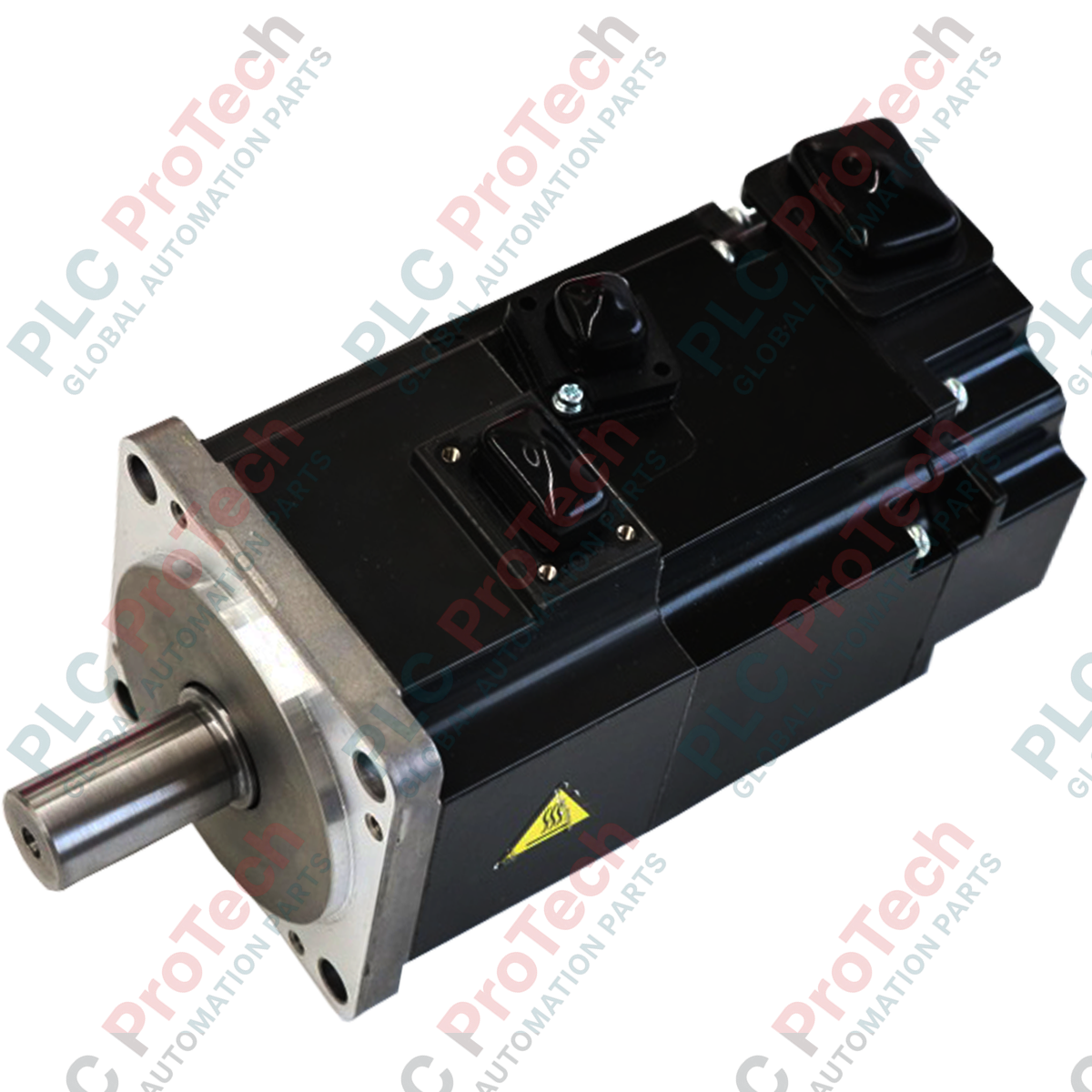
Integrating seamlessly into high-speed, precision positioning systems, the Mitsubishi Electric HG-KR73 low-inertia rotary servo motor delivers 750W (0.75 kW) of continuous power output within the high-performance MELSERVO-J4 platform. Engineered for highly dynamic applications requiring rapid acceleration and deceleration, this industrial motor features a built-in 22-bit absolute encoder providing 4,194,304 pulses per revolution for exceptional closed-loop position accuracy. Operable across multiple command interfaces, including CC-Link IE Field and SSCNET III/H via compatible MR-J4 servo amplifiers, this motor maintains excellent thermal efficiency and rotational stability in demanding environments.
Key Features
- High-resolution 22-bit absolute/incremental encoder for exceptional feedback precision.
- Low-inertia rotor design optimized for high-frequency start-stop cycles.
- Totally enclosed, self-cooling structure with an IP65 protection rating (excluding shaft axis).
- Seamless integration with MELSERVO-J4 series servo amplifiers (such as MR-J4-70B, MR-J4-70A).
- Robust environmental resilience, capable of operating in ambient temperatures up to 40 degC.
Industrial Applications
- High-speed pick-and-place assembly systems
- Semiconductor manufacturing and wafer-handling machinery
- Packaging, labeling, and filling equipment
- Multi-axis X-Y positioning stages
- Textile feed drives and small printing presses
Technical Specifications
| Parameter |
Value / Specification |
| Manufacturer |
Mitsubishi Electric |
| Model / Article Number |
HG-KR73 |
| Series Name |
MELSERVO-J4 |
| Rated Output Power |
0.75 kW (750 Watts) |
| Rated Torque |
2.4 N m |
| Maximum Torque |
8.4 N m |
| Rated Speed |
3000 r/min |
| Maximum Rotational Speed |
6000 r/min |
| Rated Current |
4.8 A |
| Maximum Current |
17.0 A |
| Rotor Moment of Inertia |
1.26 x 10^-4 kg m2 |
| Detector Type |
22-bit absolute/incremental encoder (4,194,304 pulses/rev) |
| Thermal Class |
130 (Class B) |
| Ingress Protection Rating |
IP65 (excluding shaft axis) |
| Ambient Operating Temperature |
0 to 40 degC (non-freezing) |
| Net Weight |
2.8 kg |
| Shipping Weight (Calculated) |
4.0 kg |
Empirical Engineering Insights
Alternative Models & Compatibility
The HG-KR73 is the standard-shaft, low-inertia model in the 750W class. If your installation environment exposes the motor to splashing oils, heavy cutting fluids, or high humidity, the HG-KR73J variant featuring an integrated shaft oil seal must be utilized instead. Additionally, do not mistake the HG-KR series for the ultra-low inertia HG-MR73 series; though physically identical in spatial dimensions, they feature completely distinct rotor inertia envelopes and require dedicated tuning profiles within the MR Configurator2 programming suite.
Application Pitfalls & Engineering Notes
Ensure the external load-to-motor inertia ratio does not exceed the recommended maximum of 17 times the motor's rotor inertia. Exceeding this boundary without severe gain reduction will trigger servo loop oscillation, audible high-frequency vibration, and eventual overcurrent faults (such as AL.50 or AL.51) during rapid acceleration phases. In tightly sealed control cabinets, verify that ambient motor temperature does not push past the 40 degC threshold, as continuous heavy operation near 2.4 N m rated torque can drive the internal windings close to their Class B thermal limits.
Commissioning & Wiring Tips
To prevent feedback communication dropouts, always employ dedicated, double-shielded encoder cables (such as Mitsubishi’s MR-EKCBL_M-H or MR-EKCBL_M-L cables). The 22-bit high-resolution serial feedback signal is sensitive to high-frequency electromagnetic noise; therefore, routing motor power cables and feedback lines in separate, grounded metal conduits is highly recommended. Ensure the motor frame is securely grounded back to the companion MR-J4 amplifier's earth terminal to minimize potential leakage currents.
Installation Guidelines
CRITICAL WARNING:
Verify that primary AC input power supplying the companion MR-J4 servo amplifier is completely disconnected and locked out. Wait at least 15 minutes to allow internal DC bus capacitors to fully discharge before attempting to connect or disconnect the motor power or encoder lines. Failure to do so can result in fatal electrical shock and immediate destruction of the encoder electronics.
1
Mount the motor securely on a flat, vibration-resistant metal mounting plate. Clean any rust-preventative compounds from the shaft before attaching mechanical components.
2
Align the coupling accurately; excessive misalignment will exceed the allowable radial load of 392 N and thrust load of 147 N, leading to premature bearing failure.
3
Connect the encoder and power cables, making sure they snap firmly into their respective sockets. Avoid routing the cables with sharp bends or structural tension.