Description
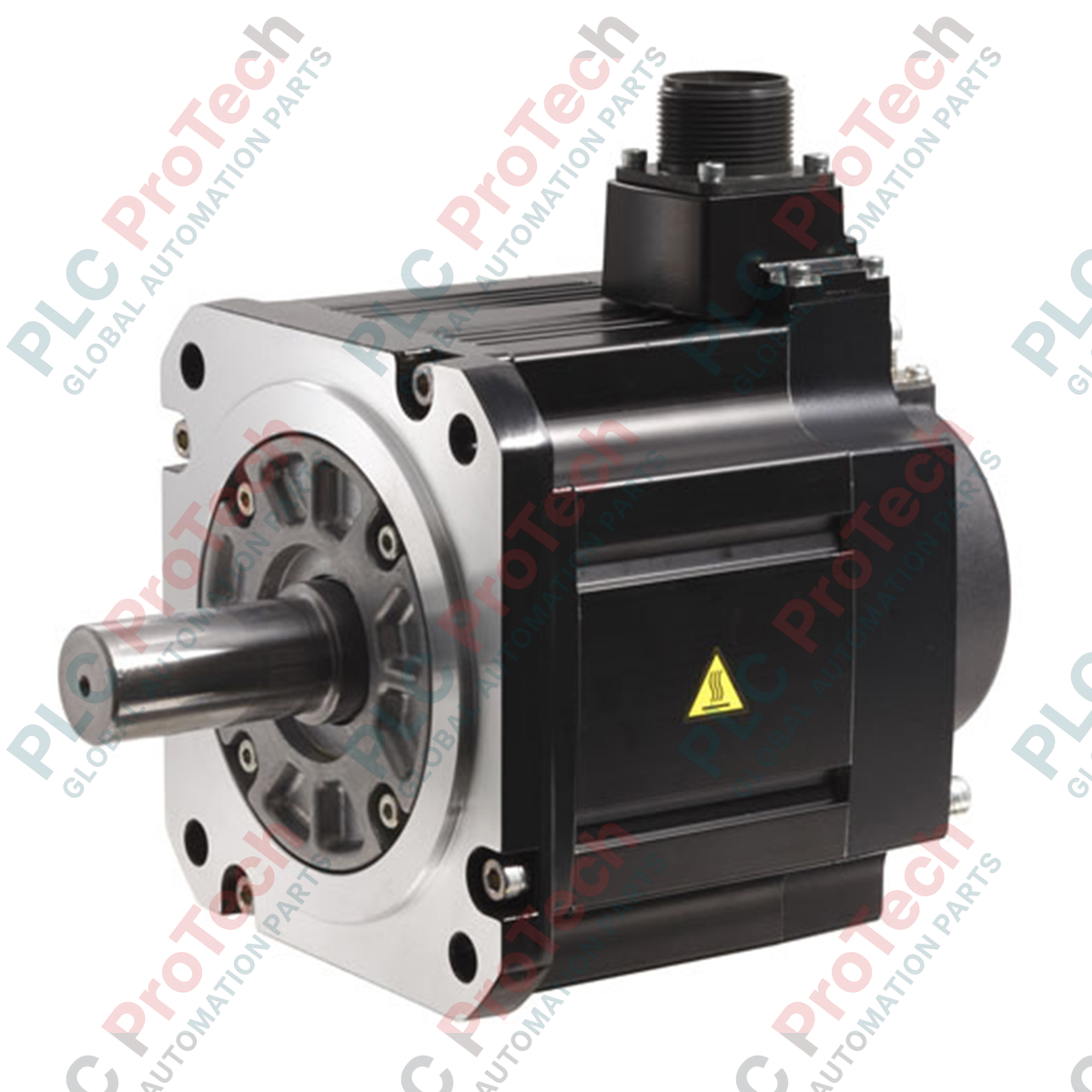
Operating within high-precision motion control architectures, the Mitsubishi Electric HG-SR102B provides robust dynamic performance as a medium-inertia rotary servo motor designed for demanding industrial automation environments. This 200V class motor delivers a rated output of 1.0 kW and operates at a rated rotational speed of 2000 r/min, offering an integrated electromagnetic safety brake designed to lock the shaft during power-off or emergency stop conditions. Equipped with a high-resolution 22-bit absolute/incremental encoder, this unit ensures exceptional positioning accuracy and velocity stability when paired with compatible MR-J4 series servo amplifiers. The fully enclosed, self-cooling structure features an IP67 protection rating, making it highly resilient against dust, moisture, and challenging factory-floor conditions.
Features
-
High-Resolution Feedback: Integrated 22-bit encoder provides 4,194,304 pulses per revolution for superior tracking and minimal velocity ripple.
-
Built-in Electromagnetic Brake: Suffix B designation indicates an integrated holding brake for vertical axis control and emergency stop scenarios.
-
Medium Inertia Design: Highly suitable for applications requiring stable load control with up to a 17:1 recommended load-to-motor inertia ratio.
-
Rugged Enclosure: Totally enclosed, self-cooled design with an IP67 protection rating (excluding the shaft-through portion).
-
Flexible Interface Compatibility: Integrates seamlessly with CC-Link IE Field, SSCNET III/H, and general-purpose pulse/analog interfaces.
Applications
- Material handling systems and high-speed transfer gantries
- Packaging, labeling, and cartoning machinery
- CNC machine tool feed axes and rotary tables
- Automated assembly lines and pick-and-place robotics
Technical Specifications Table
| Parameter |
Specification Value |
| Manufacturer |
Mitsubishi Electric |
| Model Reference |
HG-SR102B |
| Rated Output |
1.0 kW |
| Voltage Class |
200V AC |
| Rated Speed |
2000 r/min |
| Maximum Speed |
3000 r/min |
| Rated Torque |
4.8 N-m |
| Maximum Torque |
14.3 N-m |
| Rated Current |
5.6 A |
| Maximum Current |
17.0 A |
| Electromagnetic Holding Brake |
Integrated (Holding brake static friction torque: 8.5 N-m) |
| Moment of Inertia (J) |
13.8 x 10^-4 kg-m2 |
| Encoder Type |
22-bit absolute/incremental encoder (4,194,304 pulses/rev) |
| Thermal Insulation Class |
155 (F) |
| Ingress Protection Rating |
IP67 (excluding shaft passage) |
| Ambient Operating Temperature |
0 degC to 40 degC (non-freezing) |
| Net Mass |
8.2 kg |
| Shipping Weight (Calculated) |
9.3 kg |
Connections and Interfaces
Power, brake control, and encoder communication are routed through dedicated heavy-duty quick-disconnect MS connectors. Safe operation requires strict adherence to the pin mapping detailed below.
| Connector / Pin Group |
Signal Assignment |
Functional Details |
| Power Connector - Pin U |
Phase U |
Motor power phase U input |
| Power Connector - Pin V |
Phase V |
Motor power phase V input |
| Power Connector - Pin W |
Phase W |
Motor power phase W input |
| Power Connector - Pin PE |
Protective Earth (Ground) |
Motor frame ground connection |
| Brake Connector - Pin B1 / B2 |
Brake Power (24V DC) |
Non-polarized electromagnetic brake coil power |
| Encoder Connector |
Serial Data / Power |
High-speed differential serial communication link to amplifier |
Alternative Models & Compatibility
The HG-SR102B belongs to the MR-J4-compliant family of rotary servo motors, offering a direct structural upgrade path from the legacy HC-SFS102B series. This model requires MR-J4-100-class amplifiers. When transitioning from older systems, verify encoder cable interfaces as the 22-bit high-resolution serial connection protocol is not backward compatible with MR-J3 encoder wiring schemes.
Application Pitfalls & Engineering Notes
While the IP67 housing allows installation in environments with high humidity and dust, standard models are not equipped with a shaft oil seal. For applications with continuous fluid contact or oil mist at the shaft interface, engineers should specify the HG-SR102BJ variant. Ensure the holding brake is never used for dynamic deceleration; it is strictly designed as a static holding mechanism to prevent gravity-induced axis drift.
Commissioning & Wiring Tips
During initial commissioning, verify the 24V DC brake supply voltage measured directly at the motor terminals. Voltage drops across extended cable runs can cause incomplete brake release, generating excessive friction heat and triggering overcurrent alarms. Avoid routing encoder and motor power cables in the same conduit; maintain a minimum 100mm clearance to prevent electromagnetic coupling from the high-frequency switching frequency of the drive.
Installation Guidelines
CRITICAL WARNING: SAFETY COMPLIANCE
Isolate and lock out all main power lines before attempting mechanical installation or electrical terminations. Ensure that the DC bus capacitors of the associated servo amplifier have fully discharged (allow a minimum of 15 minutes post-power-off) before handling motor terminals to avoid lethal shock hazards.
1
Mount the motor on a flat, vibration-damped surface with proper alignment to prevent shaft overload. Do not hit the shaft end with a hammer during pulley or coupling installation.
2
Ensure the protective earth (PE) terminal of the motor is securely bonded to the main system electrical ground panel.
3
Verify that the cables are routed with strain relief and respect the minimum bending radius specified for dynamic cable carriers.