Description
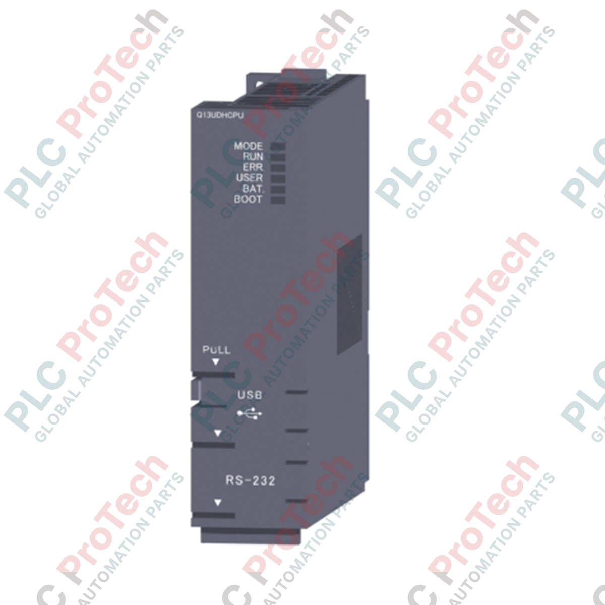
Engineered to handle high-demand industrial processing, the Mitsubishi Electric Q13UDHCPU is a high-performance Universal Q-Series PLC processor designed for complex automation architectures. Integrating state-of-the-art sequencing and structured programming execution, this module provides the computation speed and memory bandwidth required for high-speed synchronization in discrete manufacturing, packaging, and heavy process control. It integrates natively with the MELSEC Q Series backplane system, facilitating low-latency communication with digital, analog, and intelligent function modules.
Key Features
-
Rapid Instruction Execution: Achieves a processing speed of 9.5 ns for basic LD sequence instructions and 19 ns for MOV data transfer instructions.
-
Substantial Memory Allocations: Features a 130K steps program capacity paired with 520 KB of built-in program memory and 1024 KB of standard RAM.
-
Extensive Physical and Logical I/O: Controls up to 4096 physical I/O points directly, with access to 8192 device points via direct memory mapping.
-
Multi-CPU System Support: Features a high-speed multi-CPU shared memory area of 32 KB for coordinate-control architectures.
-
Flexible Programming Environments: Fully compatible with Relay Symbol, MELSAP 3 (SFC), MELSAP-L, Function Blocks (FB), and Structured Text (ST) languages.
Applications
- High-speed multi-axis assembly and automotive production lines.
- Precision electronic and semiconductor manufacturing machinery.
- Multi-tiered material handling, sorting, and warehouse logistics networks.
- Comprehensive process instrumentation systems requiring distributed I/O execution.
Technical Specifications
| Parameter |
Specification Values |
| Manufacturer |
Mitsubishi Electric |
| Model Code |
Q13UDHCPU |
| Series Type |
MELSEC Q Series (Universal QCPU) |
| Control Execution Method |
Stored program cyclic/iteration operation |
| Program Capacity |
130K steps (520 KB) |
| Standard RAM (Drive 3) |
1024 KB |
| Standard ROM (Drive 4) |
2048 KB |
| Physical I/O Points |
4096 Points (X/Y 0 to FFF) |
| Internal Current Consumption (5V DC) |
0.39 A |
| Operating Temperature Range |
0 to 55 degC (ambient) |
| Storage Temperature Range |
-25 to 75 degC |
| Module Dimensions (W x H x D) |
27.4 mm x 98 mm x 89.3 mm |
| Unit Mass |
0.20 kg |
| Shipping Weight (Calculated) |
1.2 kg |
Connections and Interfaces
| Interface Type |
Functional Assignment & Description |
| USB Port |
Mini-B physical interface; supports high-speed program upload/download and online diagnostics via GX Works2. |
| RS-232 Port |
D-Sub 9-pin interface for legacy serial communication, direct HMIs, and peripheral telemetry. |
| Memory Card Interface |
Dedicated slot accepting SRAM (up to 8 MB), Flash (up to 4 MB), or ATA cards (up to 32 MB) for database storage and firmware storage. |
Empirical Engineering Insights
Alternative Models & Compatibility
The Q13UDHCPU serves as a direct upgrade path for older Q02HCPU and Q06HCPU processors. However, note that while the form factor and backplane installation remain identical, transition from older High-Performance models to Universal models requires compiling the project configuration database inside GX Works2 and adjusting task schedules to prevent cycle timing variations due to the faster internal execution times.
Application Pitfalls & Engineering Notes
When operating multiple CPUs on a shared backplane, the high-speed CPU bus interface consumes shared memory bandwidth. Developers must configure proper interlocking structures within the 32 KB shared memory region to prevent write access overlap, which can trigger system watchdog errors (WDT) and halt process control loops.
Commissioning & Backup Strategies
To safeguard against battery decay and sudden shutdown logic corruption, commission standard ROM backups. We recommend structuring automatic firmware boot programs to load directly from Drive 4 (Standard ROM) at startup. Additionally, configure memory card partitions during initial setup using the diagnostic memory allocation utility inside the IDE.
Installation Guidelines
CRITICAL WARNING: Ensure all power to the main base unit (backplane) and external I/O terminals is completely disconnected before inserting or removing the CPU module. Failing to isolate external control voltages can result in backplane data bus corruption, permanent hardware damage, or system fault shutdowns.
1
Align the bottom guide lug of the CPU module with the base unit slot interface.
2
Gently push the top of the module forward until the secure latch locks into place on the backplane support framework.
3
Tighten the integrated security screw (where applicable) to prevent vibration-induced disconnections.
4
Connect the lithium backup battery to the designated battery terminal socket prior to running system configuration diagnostics.