Description
Integrating industrial PC-based systems directly into high-speed automation networks, the Mitsubishi Electric Q81BD-J71GP21-SX serves as a high-performance CC-Link IE Control Network interface board. It allows an industrial computer or controller to function seamlessly as either a control station or a normal station within an optical dual-loop topology. Configured for Modern PCIe architectures, this module ensures high-throughput, real-time deterministic communication for demanding distributed industrial applications.
Features
-
Dual-Station Versatility: Configurable as either a master control station or a normal local station within the network hierarchy.
-
Multi-Board Integration: Supports concurrent installation of up to 4 interface boards within a single host industrial computer.
-
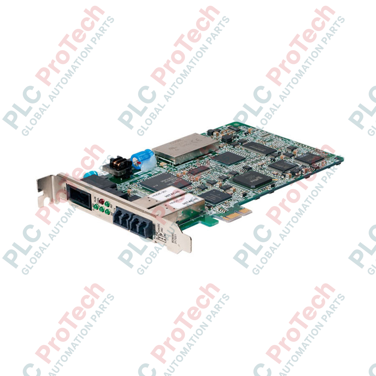
Standard PCIe Form Factor: Designed as a half-size board compatible with PCI Express x1, x2, x4, x8, and x16 physical slots.
-
Low-Latency Network Control: Utilizes optical fiber loop transmission for noise immunity and high-speed deterministic performance.
-
Single-Slot Footprint: Efficient mechanical layout occupies only 1 slot inside the PC chassis.
Applications
- High-speed PC-to-PLC data acquisition and plant-wide SCADA integration.
- Industrial PC (IPC) deployments within MELSEC automation systems.
- Real-time distributed control networks requiring redundant optical fiber loops.
- High-noise manufacturing environments requiring optical noise isolation.
Technical Specifications
| Specification Parameter |
Value / Detail |
| Manufacturer |
Mitsubishi Electric |
| Model Number |
Q81BD-J71GP21-SX |
| Product Type |
CC-Link IE Control Network PC Interface Board |
| Station Type |
Control station or normal station |
| Max Boards per PC |
Up to 4 boards |
| Installation Slot |
PCI Express x1, x2, x4, x8, x16 (half size) |
| PCI Express Spec |
Standard Rev. 1.1 (3.3 VDC, link width: 1 lane, basic clock: 100 MHz) |
| Occupied Slots |
1 slot |
| Internal Current Consumption |
2.07 A at 3.3 VDC |
| Network Connection Type |
Optical dual-loop connector (LC type duplex) |
| Weight |
0.13 kg (0.28 lbs) |
| Shipping Weight (Calculated) |
1.50 kg (3.30 lbs) |
Connections and Interfaces
| Interface / Connection Port |
Functional Assignment / Description |
| IN (Optical Port) |
Receiving port for the CC-Link IE Control redundant optical fiber loop. |
| OUT (Optical Port) |
Transmitting port for the CC-Link IE Control redundant optical fiber loop. |
| PCIe Edge Connector |
PCI Express Standard Rev 1.1 compliant 1-lane bus interface for host communication and 3.3 VDC power supply. |
Empirical Engineering Insights
Based on industrial deployment data, maintaining clean fiber-optic interfaces is critical for long-term transmission stability.
Alternative Models & Compatibility
When migrating legacy industrial computer systems from PCI-bus models (such as the Q80BD-J71GP21-SX) to this PCIe-based alternative, you must update the CC-Link IE Control utility software on the host. While the physical interface shifts from a standard PCI edge connector to a PCI Express x1 connection, the application layer configuration within the SW1DND-CCIEF-B software remains backward compatible.
Application Pitfalls & Engineering Notes
This module pulls a high peak current of 2.07 A at 3.3 VDC directly from the motherboard's PCIe slot. When configuring systems that utilize the maximum of 4 boards in a single host PC, ensure the industrial PC motherboard and power supply are specifically rated to support up to 8.28 A on the 3.3 VDC rail. General-purpose office motherboards frequently suffer from voltage instability when loaded with multiple high-current PCIe expansion boards, causing intermittent network timeouts.
Commissioning & Wiring Tips
Ensure only high-quality graded-index (GI) multi-mode fiber-optic cables (50/125 micrometer) with LC connectors are utilized. Always connect the OUT port of one station to the IN port of the adjacent station in a continuous loop. Dust caps must remain secured on any unused transceivers to prevent environmental debris from degrading the optical transmitter assembly; clean all fiber tips with a dedicated dry optic cleaner prior to final insertion.
Installation Guidelines
CRITICAL WARNING: Disconnect all primary power from the industrial computer before installing or removing this PCI Express card. Wait at least 30 seconds to allow the motherboard power supply and filter capacitors to fully discharge. Failure to follow this procedure can cause catastrophic electrostatic damage (ESD) to the PCIe interface chip.
1
Wear an approved ESD grounding wrist strap attached to an unpainted chassis ground on the PC cabinet.
2
Remove the computer cover and locate an empty PCI Express slot (x1 or wider) with its bracket removed.
3
Carefully align the edge connector of the interface card with the slot and press straight down until fully seated.
4
Secure the card's mounting bracket with a retention screw or chassis latch mechanism, then replace the computer cover.