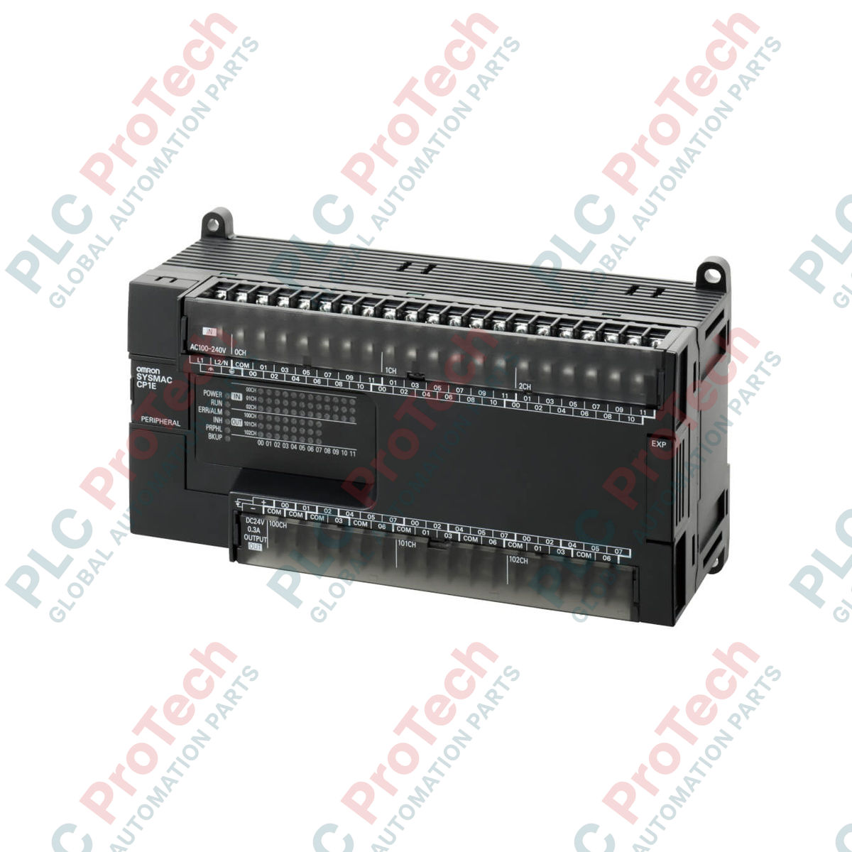
Description
Engineered for basic standalone machine automation, the Omron CP1E-E30SDR-A serves as an entry-level controller within the CP1E Series CPU Unit family. This compact controller consolidates power supply, processing capability, and digital input/output interfaces into a single integrated housing, minimizing control panel footprint. Featuring an direct-connection USB 2.0 port, it allows for direct programming and debugging without the need for specialized external conversion adapters. With 30 integrated I/O points consisting of 18 DC inputs and 12 relay outputs, it provides a stable and highly reliable platform for cost-sensitive automation architectures operating on standard 100 to 240 VAC power.
Features
-
Monolithic Form Factor: Integrates CPU, 100-240 VAC power supply, and I/O logic in a single compact enclosure to optimize cabinet space.
-
Built-In USB Port: Standard USB Type-B peripheral port simplifies connection for programming, diagnostics, and monitoring via CX-Programmer.
-
Basic E-Type Logic: Optimized instruction set designed for straightforward ladder logic execution in non-expandable applications.
-
Robust Memory Architecture: Features 2k steps of internal program memory and 2k words of data memory to handle standard automation sequences.
-
High-Speed Counters: Supports quick signal processing for rotary encoders or pulse feedback sensors via built-in high-speed inputs.
Applications
-
Conveyor and Sorting Systems: Managing material handling, line routing, and simple motor control in logistics.
-
Packaging Machinery: Controlling automated sealing, wrapping, and labeling systems with basic sensor-actuator feedback loops.
-
HVAC and Pump Control: Sequencing exhaust fans, circulating pumps, and environmental ventilation systems.
-
Small Utility Equipment: Automating automatic gate operations, car wash sequences, and industrial washing stations.
Technical Specifications Table
| Specification Parameter |
Value / Details |
| Manufacturer |
Omron |
| Model Code |
CP1E-E30SDR-A |
| Series Class |
CP1E (Basic E-type S-renewal) |
| Supply Voltage |
100 to 240 VAC (50/60 Hz) |
| Operating Voltage Range |
85 to 264 VAC |
| Power Consumption |
15 VA max. (at 100 to 240 VAC) |
| Total Built-In I/O Capacity |
30 I/O points |
| Built-In Inputs |
18 points (24 VDC inputs) |
| Built-In Outputs |
12 points (Electromechanical relay outputs) |
| Programming Interface |
USB 2.0 peripheral port (Type-B) |
| Memory Allocation |
Program: 2k steps / Data: 2k words |
| Ambient Operating Temperature |
0 to 55 degC (no icing/condensation) |
| Unit Dimensions |
78 mm x 130 mm x 90 mm (L x W x H) |
| Net Unit Weight |
0.67 kg |
| Shipping Weight (Calculated) |
2.00 kg |
Connections and Interfaces
| Terminal Cluster |
Terminal Label |
Function Description |
| Top Power & Input Block |
L1, L2/N |
Main AC operational power supply input (100 to 240 VAC) |
| COM |
Common terminal for internal 24 VDC inputs |
| 0.00 to 1.05 |
18 Discrete DC input points split across word address spaces |
| Bottom Output Block |
COM (00 to 03) |
Common contact points for output relay channels |
| 100.00 to 101.03 |
12 Mechanical relay output channels |
Empirical Engineering Insights
Alternative Models & Compatibility
The CP1E-E30SDR-A is an "E-type" (Basic) model and cannot be expanded with CP1W option boards or standard CP1W expansion units. Systems that scale up to require additional I/O, RS-232C, RS-422, or RS-485 serial communications must transition to the "N-type" (Application) or "NA-type" CPU options, such as the CP1E-N30SDR-A, which natively support option boards and communication expansion modules.
Application Pitfalls & Engineering Notes
Because this model is equipped with relay outputs, it is subject to mechanical wear and electrical contact erosion. Do not use the integrated relay outputs for high-frequency PID control loop outputs or high-speed pulse-train generation. If high-speed switching is necessary, either install external solid-state switches or select the transistor-output variant of this PLC family.
Commissioning & Wiring Tips
Always route the operational AC supply wiring (L1/L2) physically separate from the low-voltage DC input cables. It is critical to establish a solid ground connection at the protective earth (PE) terminal using a dedicated grounding conductor (resistance below 100 ohms) to minimize electric noise coupling from surrounding high-power switchgear or variable frequency drives (VFDs).
Installation Guidelines
CRITICAL WARNING:
Completely isolate and lock out all upstream power sources before making electrical physical contact with the terminal screws. High-voltage hazard on L1 and L2 terminals. Verify all terminal safety shields are securely locked back in place after wiring is finalized and prior to main breaker activation.
1
Position the CPU unit on a standard 35 mm DIN rail, applying uniform pressure until the integral plastic mounting track clip engages with a distinct lock sound.
2
Affix mechanical DIN rail stop clips on either end of the PLC module to eliminate any potential physical shift during machine-induced vibration.
3
Terminate the input, output, and AC supply wiring using insulated M3 crimp ring or spade terminals, torque-tightening each terminal screw strictly to 0.5 N-m.