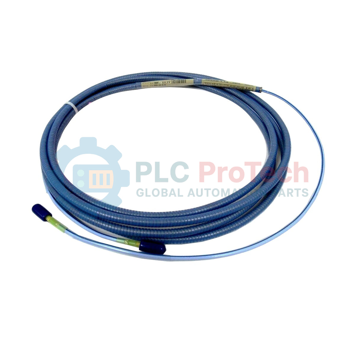
Description
Serving as a critical signal transmission link within turbine supervisory instrumentation architectures, the Bently Nevada 330854-040-25-CN bridges the gap between proximity probes and sensor housings to deliver precise displacement data. Engineered specifically for the 3300 XL 25 mm Proximity Transducer System, this cable provides impedance-matched signal paths to guarantee optimal calibration stability and prevent signal loss over distance. It features a robust Armored High Temperature FluidLoc design, preventing environmental fluids from wicking through the cable shield while ensuring maximum physical protection in severe industrial environments.
Features
-
Impedance-Matched Engineering: Constructed as a 75 ohm triaxial cable to preserve transducer calibration integrity.
-
FluidLoc Cable Technology: Prevents process fluids, moisture, and oils from migrating internally through the cable structure.
-
High-Temperature Durability: PFA-insulated core capable of withstanding extreme environmental shifts.
-
Integral Armor: Protective stainless steel armor sheath prevents mechanical pinching, abrasions, and routing damage.
Applications
- Steam, gas, and hydro turbine shaft vibration monitoring systems.
- Thrust and radial bearing displacement measurements in heavy industrial rotating machinery.
- High-temperature and fluid-exposed balance-of-plant auxiliary equipment monitoring.
Technical Specifications
| Specification Parameter |
Value / Rating |
| Manufacturer |
Bently Nevada |
| Model Reference |
330854-040-25-CN |
| System Compatibility |
3300 XL 25 mm Proximity Transducer System |
| Cable Length Option |
4.0 meters (13.1 feet) |
| Cable Construction |
75 ohm Triaxial, Perfluoroalkoxyethylene (PFA) insulated FluidLoc |
| Armor Option |
Armored High Temperature FluidLoc Cable |
| Capacitance |
69.9 pF/m (21.3 pF/ft) typical |
| Operating & Storage Temp |
-35 degC to +200 degC (-31 degF to +392 degF) |
| Agency Approvals |
CN (Country-Specific Approvals) |
| Net Weight |
0.140 kg (0.31 lbs) |
| Shipping Weight (Calculated) |
1.50 kg (3.30 lbs) |
| Package Dimensions (Calculated) |
8.89 cm x 11.70 cm x 24.10 cm (3.50 in x 4.60 in x 9.50 in) |
| Country of Origin |
United States (U.S.A.) |
Empirical Engineering Insights
Alternative Models & Compatibility
This cable is highly specialized for 25 mm systems. You must avoid attempting to pair this with 5 mm, 8 mm, or 11 mm proximity systems. Subsystem component mismatches alter the overall system impedance and capacitance, which will generate major calibration errors. Ensure that the combined length of your proximity probe and this extension cable perfectly matches the targeted system length (typically 5.0 or 9.0 meters total) as designated by your Proximitor sensor calibration parameters.
Application Pitfalls & Engineering Notes
Although the FluidLoc option offers excellent resistance to process fluid wicking, care must be taken during cable routing. The minimum bend radius of the armored outer sheath must be strictly maintained (minimum of 25.4 mm or 1.0 inch) to prevent structural kinking. Mechanical stress or over-bending can lead to shielding fractures, showing up as high-frequency intermittent spikes or false vibration trips on the turbine monitoring rack.
Commissioning & Wiring Tips
Before locking the miniature coaxial connectors, thoroughly clean the connection interfaces with an approved electrical contact cleaner or isopropyl alcohol. Moisture or dirt trapped in the connector will degrade isolation resistance, leading to calibration drifts. Ensure the connectors are hand-tightened until a physical "click" is felt, then slide a protective connector boot or wrap with self-fusing silicone tape to prevent ground loops and ambient contaminant ingress.
Installation Guidelines
CRITICAL WARNING
Isolate and de-energize the machine and monitoring rack before starting extension cable replacement or installation. Failure to disconnect active proximity circuits can result in unexpected monitoring system trips or electrostatic damage to sensitive internal transducer components.
1
Route the armored cable through dedicated protective conduit paths away from high-power alternating current (AC) cables to eliminate electromagnetic interference.
2
Connect the extension cable to the proximity probe's integral lead cable. Tighten until the positive locking mechanism engages fully.
3
Insulate the coaxial connector junction from the surrounding machine metal or conduit structure using a connector protective boot or self-fusing tape to prevent unwanted ground loop interference.
4
Verify total loop capacitance using a calibrated multimeter before re-energizing the Proximitor sensor for operation.