Description
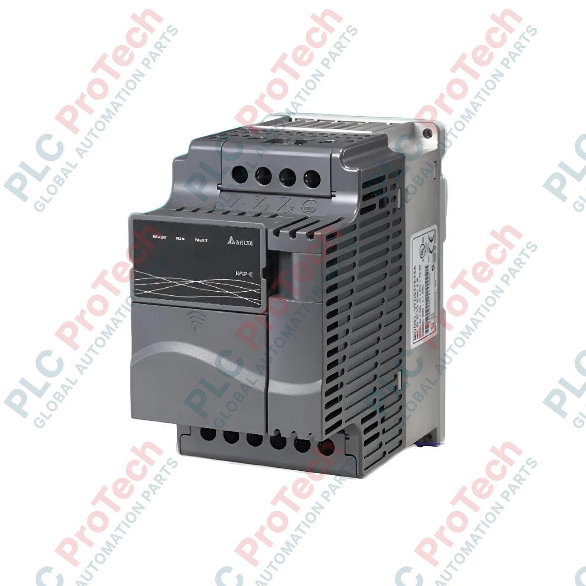
Providing precise sensorless vector control for demanding three-phase industrial applications, the Delta VFD150E23A is an adjustable frequency AC motor drive engineered within the high-performance VFD-E Series platform. This 15 kW (20 HP) drive is configured for 230V three-phase mains input, supplying reliable motor speed control, exceptional torque response, and versatile system integration capabilities. Designed as a modular, standard drive configuration, it features a built-in PLC function with 500-step execution capacity, enabling basic logic sequencing without requiring external controller hardware.
Features
-
Flexible Control Modes: Supports sensorless vector control (SVC) and traditional V/F control curves to match specific load characteristics.
-
Modular Architecture: Enables field-installation of extension cards for additional digital/analog I/O, relay outputs, or encoder feedback.
-
Integrated Micro PLC: Built-in ladder logic execution capability (500 steps) for local control sequence programming.
-
Compact Housing: Optimized layout allows side-by-side mounting to maximize physical control panel density.
-
Comprehensive Protection: Implements overcurrent, overvoltage, undervoltage, overheating, overload, and phase-loss protections.
Applications
-
Conveying and Material Handling: Speed synchronization and soft start-stop control for heavy industrial belts and roller systems.
-
Fluid and Air Movement: Closed-loop pressure and flow control for industrial water pumps, exhaust fans, and blowers.
-
Machinery Control: Reliable torque delivery for woodworking equipment, milling spindles, and manufacturing assembly machines.
Technical Specifications
| Manufacturer |
Delta Electronics |
| Model Number |
VFD150E23A |
| Product Series |
VFD-E Series |
| Applicable Motor Capacity |
15 kW / 20 HP |
| Input Power Supply Rating |
230V AC, Three-Phase |
| Drive Version |
Standard Drive Type (A) |
| Net Weight |
6.6 kg |
| Shipping Weight (Calculated) |
8.0 kg |
Alternative Models & Compatibility
The VFD150E23A functions as a high-capacity unit within the VFD-E family. It is form-factor and program compatible with other E Series models of similar frame sizes, though commissioning parameter configurations should be reviewed when replacing older VFD-S or VFD-M series modules due to updated registers and terminal block layouts. The "A" suffix confirms a standard physical configuration with integrated keypad housing.
Application Pitfalls & Engineering Notes
When deploying this 15 kW drive in confined enclosures, thermal management is critical. At full load, ensure surrounding ambient air temperatures do not exceed 40 degC without derating. If side-by-side mounting is utilized, the protective top stickers must be removed from the drive housing to ensure maximum convective heat dissipation through the vertical venting pathways.
Commissioning & Wiring Tips
Prior to automated serial communication setup, verify that control parameters for Modbus RTU communications (Pr.09.00 through Pr.09.04) are explicitly defined. Connect communication shielding to a low-impedance earth ground at the drive-end chassis only. If the drive exhibits spurious overvoltage tripping during decelerations, evaluate mechanical load inertia and parameterize deceleration ramp times accordingly, or mount an external braking resistor to the dedicated +1 and B1 terminal connections.
Installation Guidelines
CRITICAL WARNING: Hazardous residual electrical voltage remains present in the internal DC bus capacitors after mains input power is disconnected. Prior to initiating terminal wiring, structural mounting, or servicing, de-energize all incoming power feeds and wait a minimum of 10 minutes. Use a verified digital multimeter to measure and confirm zero voltage across terminals +1 and - before touching any internal electrical conductors.
1
Mount the drive vertically to a flat, rigid backplate using specified torque mounting bolts to prevent structural vibration. Ensure at least 120 mm of clear space is maintained above and below the cooling heatsink assembly.
2
Terminate the incoming three-phase 230V power utility conductors to terminal blocks R/L1, S/L2, and T/L3. Connect the output motor cables directly to terminals U/T1, V/T2, and W/T3.
3
Establish a low-impedance ground connection to the dedicated ground screw. Run all low-voltage control and analog signal wiring in separate, shielded conduit runs distinct from high-power AC lines to eliminate electromagnetic noise coupling.